- Published on
VMware vSphere
- Authors
- Name
- Jackson Chen
VMwaer vSphere documentation
https://docs.vmware.com/en/VMware-vSphere/index.html
ESXi Installation and Setup
ESXi Host Installation and Setup
vSphere Networking
vSphere 7 Update 2 Networking Guide
Reference Sites and Reading
https://www.simongreaves.co.uk/vsphere/
vSphere and vCenter Security Guide
vSphere and vCenter Server v7.0 Update 2 Security Guide
vSphere and vCenter 7 Update 2 Security Guide
vSphere Storage Guide
vSphere 7 Storage Guide
vSphere and vCenter 7.0 High Availability Guide
vSphere and vCenter 7.0 High Availability Guide
vSphere and vCenter Monitoring and Performance
vSphere and vCenter Monitoring and Performance Guide
vSphere and vCenter 7.0 Update 2 Monitoring and Performance Guide
Performance Best Practices for VMware vSphere 6.7
Performance Best Practices for VMware vSphere 6.7
vSphere Virtual Machine Administration
vSphere Virtual Machine Administration
vSphere Replication Administration
VMware vSphere Replication Administration
VMware vSphere Replication Security
VMware vSphere Replication Security
vSphere Resource Management
vSphere Availability
Managing Host and Cluster Lifecycle
Managing Host and Cluster Lifecycle
VMware Validated Design
Architecture and Design - VMware Validated Design 5.0
Key Concepts
Software Defined Datacenter - SDDC
In a software defined datacneter (SDDC), all infrastructure is virtualized, the control of the datacenter is automated by software, vSphere is the foundation of the SDDC.
VMware Clound Foundation
It is a unified SDDC platform that bundles vSphere, includes ESXi and vCenter sever, vSAN, and NSX into a natively integrated stack to deliver enterprise ready cloud infrastructure.
Virtual Switch
It functions like physical switch, forwards frames at the data link layer. An ESXi host might contain multiple virtual switches. VMNICs is the outbound ethernet adapter. VMNICs provide NIC teaming capability.
# Security
1. Virtual switch can not interconnect
2. Netowrk traffic can not flow directly from one switch to another on the same ESXi host
VMFS and and datastore
- VMFS uses distributed journaling of its file sysetm metadata changes for fast and resilient recovery if a hardware failure occurs.
- Increases resource usage by providing VMs with shared access to a consolidated pool of clustered storage
VMFS provides an interface to storage resources, so that storage protocols, such as Fibre Channnel, Fibre Channel over Ethernet, and iSCSI, can be used to access datastore on which VM resides.
1. Dynamic growth
    a. Aggregation of storage resources
    b. Dynamic expansion of VMFS datastore
2. Dynamic locking methods of the storage resources
vSphere 7 Bitfusion
By creating pools of GPU resources, vSphere Bitfusion provides elastic infrastructure for artificial intelligence and machine learning workloads. With Bitfusion, GPUs can be shared in a way that is similar to vSphere shares CPUs.
User interfaces for accessing vCenter Server system and ESXi hosts
There are different accessing methods to interact with vCenter server and ESXi host
1. vCenter Server
    a. vSphere Client
        https://<vCenter>/ui    # Internally redirects to port 9443 on vCenter server
    b. vCenter Server Appliance Management Interface (VAMI)
        https://<vCenter>:5480
2. PowerCLI
        Connect-VIServer -Server <vCenter|ESXihost>
3. ESXi Host
    a. VMware host client
        https://<esxi>/ui
    b. Direct Console User Interface (DCUI)
        Direct console access
4. ESXCLI
    a. SSH access
    b. console access
ESXi
ESXi is a hypervisor and has the following features:
1. High security
    a. Host based firewall
        ESXi includes a firewall between the management interface and the network
    b. Memory hardening
    c. Kernel module integrity
    d. Trusted Platform Module (TPM 2.0)
    e. UEFI secure boot
    f. Encrypted core dumps
    g. Lockdown mode
        Deactivates login and API functions from being executed directly on an ESXi host
2. Installable on hard disks, SAN LUNs, SSD, USB devices, SD Cards, NVMe disk, diskless hosts
    Note: ESXi can be installed on diskless host (directly into memory) with vSphere Auto Deploy
ESXi - UEFI Secure Boot
Secure boot is part of the UEFI firmware standard. With secure boot enabled, a machine refuses to load any UEFI driver or app unless the operating system bootloader is cryptographically signed. Starting with vSphere 6.5, ESXi supports secure boot if it is enabled in the hardware.

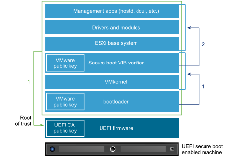

With secure boot enabled, the boot sequence proceeds as follows
- Starting with vSphere 6.5, the ESXi bootloader contains a VMware public key. The bootloader uses this key to verify the signature of the kernel and a small subset of the system that includes a secure boot VIB verifier.
- The VIB verifier verifies every VIB package that is installed on the system.
vSphere Installation Bundle (VIB)
https://blogs.vmware.com/vsphere/2011/09/whats-in-a-vib.html
VIB is the building block of an ESXi image. At a conceptual level a VIB is somewhat similar to a tarball or ZIP archive in that it is a collection of files packaged into a single archive to facilitate distribution. VIB is comprised of three parts:
a. A file archive
    VIB payload, contains the files that make up the VIB
b. An XML descriptor file
    Describes the contents of the VIB
c. A signature file
    An electronic signature used to verify the level of trust associated with the VIB
How do I add or remove VIBs from an active ESXi host
You can use the ESXCLI command to interactively query and manage the VIBs installed on a host. In addition, you can also import a software bundle into Update Manager and use it to manage the VIBs installed on the host.
Configure ESXi using DCUI
You can use the Direct Console User Interface (DCUI) to enable local and remote access to the ESXi Shell. You access the Direct Console User Interface from the physical console attached to the host. After the host reboots and loads ESXi, press F2 to log in to the DCUI. Enter the credentials that you created when you installed ESXi.
https://techgenix.com/understanding-vmware-esxi-direct-console-user-interface-dcui/
Press F2 to start the customizing ESXi system settings. Administrators use the DCUI to configure root access settings.
Configure ESXi settings using Direct Console User Interface
The Direct Console User Interface (DCUI) is a menu-based interface that is accessed from the host console and used to configure ESXi running on vSphere hosts.
1. After the server reboots and fully loads ESXi, press F2 to log in to the DCUI.
2. Enter the credentials that were created during the ESXi installation, and then press Enter.
3. From the System Customization menu, select Configure Management Network.
    a. Host name
4. From the VLAN (Optional) menu, press Enter.
    NOTE: Step 4 is mandatory although the name of the menu item includes the word optional.
5. Enter the required management VLAN ID, and then press Enter.
6. Select IPv4 Configuration and press Enter.
7. Select Set static IPv4 address and press the spacebar.
8. Enter the IPv4 Address,Subnet Mask, and the Default Gateway, and then press Enter to confirm.
9. Select DNS Configuration, and then press Enter.
10. Enter the IP addresses of the DNS servers and FQDN of the host.
    Set custom DNS suffixes
11. Press Esc to return to the main menu, and then press Y to confirm the changes and restart the management network.
12. From the main menu, click Test Management Network.
    The target IP addresses and DNS hostname are pre-populated.
13. Press Enter to perform the network test, and after the test is completed, press Enter to return to the main menu.
    CAUTION: If the network test fails, troubleshoot and resolve the issues before proceeding further.
14. From the main menu, select Troubleshooting Options
    a. Enable ESXi Shell,
    b. Enable SSH (required during validation and deployment phases) to enable the ESXi shell.
        Note: Disable SSH after deployment
    c. Modify DCUI idle timeout
15. Press Esc to return to the main menu.
DCUI ssh access
https://kb.vmware.com/s/article/2039638
You must access the DCUI to troubleshoot issues and if there are no remote management tools available, such as DRAC, iLo, or RSA, to access the ESXi host. SSH access has been enbled.
# Access DCUI from SSH session
#>  dcui
#> Ctrl + c     # Exit
Accessing the hidden command line interface
If you REALLY need access to a command line on an ESXi server, there is a completely unsupported and hidden ESXi command line interface.
To access it, on the server consolepress Alt-F1 then type unsupported and press enter. From here, you will need to type the root password and you will get a command prompt access.
Controlling remote access to an ESXi host
You can use the vSphere Client to customize essential security settings that control remote access to an ESXi host:
- The ESXi firewall is activated by default. The firewall blocks incoming and outgoing traffic, except for the traffic that is activate in the host’s firewall settings.
- Services, such as the NTP client and the SSH client, can be managed by the administrator.
- Lockdown mode prevents remote users from logging in to the host directly. The host is accessible only through the DCUI or vCenter Server.
1. Login to vSphere client
2. Access Host and Cluster, then expand vCenter -> Datacenter -> Cluster
3. Select the ESXi host, then select Configure on the right pane
4. Under System, select and configure
    a. Firewall
    b. Services
    c. Security Profile
Extract and Configure a Host Profile from the Reference Host
After provisioning the first host, you can extract and configure a host profile that can be used to apply the same configuration to other target hosts. Configuration that differs for different hosts, such as a static IP address, can be managed through the host customization mechanism.
vSphere Auto Deploy can provision each host with the same host profile. vSphere Auto Deploy can also use host customization that allows you to specify different information for different hosts. For example, if you set up a VMkernel port for vMotion or for storage, you can specify a static IP address for the port by using the host customization mechanism.
# Procedure
1. Use the vSphere Client to connect to the vCenter Server system that manages the vSphere Auto Deploy server.
2. Click Policies and Profiles and select Host Profiles.
3. Click Extract Host Profile.
4. On the Select host page of the wizard, select the reference host that you configured earlier and click Next.
5. On the Name and Description page of the wizard, enter a name and description for the new profile and click Finish.
6. Select the host profile that you want to edit and click the Configure tab.
7. Click Edit Host Profile.
8. Select Security and Services > Security Settings > Security > User Configuration > root.
8. From the Password drop-down menu, select User Input Password Configuration.
9. Click Save to configure the host profile settings.
Virtual Machine Management
vSphere Virtual Machine Administration describes how to create, configure, and manage virtual machines in the VMware vSphere® environment.
Provisioning virtual machines
Different methods to create VM
1. Use New Virtual Machine wizard
    a. vSphere Client
    b. VMware Host Client
2. PowerCLI
Creating a virtual machine from vSphere Client (vCenter UI)
From vSphere Client (vCenter UI), right-click any inventory object that is a valid parent object of a virtual machine, such as a data center, folder, cluster, resource pool, or host, and select New Virtual Machine.
Creating a virtual machine from VMware Host Client (ESXi Host UI)
Deploy VM from template or format
VMs can be deployed in the following format:
1. existing templates or clones
2. OVF format
Deploying OVF and OVA Templates
OVF is a file format that supports exchange of virtual appliances across products and platforms.
- OVF template contains multiple files in the OVF package
- OVA is a single-file distribution of the same file package
An virtual machine or vApp can be exported to an OVF template. An OVF template captures the state of a virtual machine or vApp into a self-contained package. The disk files are stored in a compressed, sparse format.
VMware Tools
https://docs.vmware.com/en/VMware-Tools/index.html
VMware Tools is a set of services and modules that enable several features in VMware products for better management of guests operating systems and seamless user interactions with them.
VMware Tools has the ability to:
- Pass messages from the host operating system to the guest operating system.
- Customize guest operating systems as a part of the vCenter Server and other VMware products.
- Run scripts that help automate guest operating system operations. The scripts run when the power state of the virtual machine changes.
- Synchronize the time in the guest operating system with the time on the host operating system
Benefits and features includes:
a. Device drivers
    VGA display
    VMXNET/VMXNET3
    Balloon driver for memory management
    Sync driver for quiescing I/O
b. Increased graphics performance
c. Improved mouse performance
3. Guest OS heartbeat service
When you install VMware Tools, you install these items:
a. The VMware Tools service
    This service synchronizes the time in the guest operating system with the time in the host operating system.
b. A set of VMware device drivers, with additional Perfmon monitoring options.
c. A set of scripts that helps you automate guest operating system operations.
Open VM Tools
https://github.com/vmware/open-vm-tools
Open VM Tools (open-vm-tools) is the open source implementation of VMware Tools for Linux guest operating systems, such as RHEL, SUSE, Ubuntu, etc
The open-vm-tools suite includes the following packages:
1. vmtoold
    The core open-vm-tools package contains the core open-vm-tools user space utilities, application programs, and libraries, including vmtoolsd, to help effectively manage communication between your host and guest OSs.
2. open-vm-tools-desktop
    optional package and includes additional user programs and libraries to improve the interactive functionality of desktop operations of your virtual machines
3. open-vm-tools-devel package
    contains libraries and additional documentation for developing vmtoolsd plug-ins and applications
4. open-vm-tools-debuginfo package
    contains the source code for open-vm-tools and binary files
VMware Tools AppInfo Plug-In
https://cloud.vmware.com/community/2020/01/17/application-discovery-vsphere-vmware-tools-11/
AppInfo in VMware Tools 11 lets you collect and publish “raw” running application processes within a GuestOSFind, ready to be consumed by standard VMware Automation Tools.
AppInfo is a new plugin within VMware Tools that enables the collection of the “raw” running application processes within a GuestOS. Once enabled, this information is then published into new VM guestinfo property called guestinfo.appinfo which can then be consumed by standard vSphere Automation Tools. By default, this new AppInfo capability is enabled by default after installing VMware Tools 11 and is supported with both Windows and Linux GuestOS.
# Configure AppInfo plug-in
esxcli vm appinfo get   # get the appinfo plug-in state of the vm
esxcli vm appinfo set --enabled {True | False}  # configure plug-in state
Virtual machine files
https://www.ibm.com/support/pages/detailed-description-all-files-make-virtual-machine
https://www.sciencedirect.com/topics/computer-science/virtual-machine-file
A virtual machine consists of several files that are stored on a storage device. The key files are the configuration file, virtual disk file, NVRAM setting file, and log file. You configure virtual machine settings through the vSphere Client, ESXCLI, or the vSphere Web Services SDK.
# Virtual Machine Files
File    Usage           Description
--------------------------------------------------------------
.vmx    vmname.vmx      Virtual machine configuration file
.vmxf   vmname.vmxf     Additional virtual machine configuration files
.vmdk   vmname.vmdk     Virtual disk characteristics
-flat.vmdk  vmname-flat.vmdk    Virtual machine data disk
.nvram  vmname.nvram or nvram   Virtual machine BIOS or EFI configuration
.vmsd   vmname.vmsd     Virtual machine snapshots
.vmsn   vmname.vmsn     Virtual machine snapshot data file
.vswp   vmname.vswp     Virtual machine swap file
.vmss   vmname.vmss     Virtual machine suspend file
.log    vmware.log      Current virtual machine log file
-#.log  vmware-#.log    Old virtual machine log files
        (where # is a number starting with 1, up to 6)
        such as -1.log, -2.log
Additional files are created when you perform certain tasks with the virtual machine.
.hlog file
    It is a log file that is used by vCenter Server to keep track of virtual machine files that must be removed after a certain operation completes.
.vmtx file
    It is created when you convert a virtual machine to a template. The .vmtx file replaces the virtual machine configuration file (.vmx file).
Virtual machine hardware
The virtual machine compatibility setting determines the virtual hardware available to the virtual machine, which corresponds to the physical hardware available on the host.
Hardware Features Available with Virtual Machine Compatibility Settings
Note: It provides detail list of hardware features and ESXi version support matrix
https://4sysops.com/archives/vsphere-7-0-upgrade-virtual-vm-hardware-and-vmware-tools/
Noet: You can't upgrade VM hardware on VCSA or even update VMware Tools on the appliance.
      It is not supported by VMware.
Not all devices are available to add and configure. For example, you cannot add video devices, but you can configure available video devices and video cards.
You can add multiple USB devices, such as security dongles and mass storage devices, to a VM that resides on an ESXi host to which the devices are physically attached.
Snapshots are not supported with vSphere DirectPath I/O pass-through devices.
Virtual Machine Communication Interface (VMCI)
The Virtual Machine Communication Interface (VMCI) is an infrastructure that provides a high-speed communication channel between a VM and the hypervisor. You cannot add or remove VMCI devices.
# The following types of communication are available:
1. Datagrams
    Connectionless and similar to UDP queue pairs
2. Connection oriented
    Similar to TCP
What must be done before upgrading the VMware virtual hardware version
Before you upgrade the virtual hardware, you should always create a backup or snapshot of your VM(s) and update your VMware Tools
Upgrade VMware Tools for multiple VMs at the cluster level
Simply select multiple VMs in the VM view. Then right-click and select Guest OS > Install/Upgrade VMware Tools.
CPU and Memory
Virtual CPU Configuration
1. A virtual machine cannot have more virtual CPUs than the actual number of logical CPUs on the host
2. The maximum number of virtual CPUs per vSphere Fault Tolerance VM remains at 8
Configuring multicore virtual CPUs.
You configure how the virtual CPUs are assigned in terms of cores and cores per socket. Determine how many CPU cores you want in the virtual machine, then select the number of cores you want in each socket, depending on whether you want a single-core CPU, dual-core CPU, tri-core CPU, and so on. Your selection determines the number of sockets that the virtual machine has.
1. The maximum number of virtual CPU sockets that a virtual machine can have is 128.
2. You can configure a virtual machine with ESXi 7.0 Update 1 and later compatibility to have up to 768 virtual CPUs.
3. If you want to configure a virtual machine with more than 128 virtual CPUs, you must use multicore virtual CPUs.
Virtual Storage
Virtual disks are connected to virtual storage adapters.
# ESXi accesses the adapters directly through device drivers in the VMkernel:
1. BusLogic Parallel: The latest Mylex (BusLogic) BT/KT-958 compatible host bus adapter.
2. LSI Logic Parallel: The LSI Logic LSI53C10xx Ultra320 SCSI I/O controller is supported.
3. LSI Logic SAS: The LSI Logic SAS adapter has a serial interface.
4. VMware Paravirtual SCSI: A high-performance storage adapter that can provide greater throughput and lower CPU use.
5. AHCI SATA controller: Provides access to virtual disks and CD/DVD devices.
   The SATA virtual controller appears to a VM as an AHCI SATA controller.
   AHCI SATA is available only for VMs with ESXi 5.5 and later compatibility.
6. Virtual NVMe: NVMe is an Intel specification for attaching and accessing flash storage devices to the PCI Express bus.
   NVMe is an alternative to existing block-based server storage I/O access protocols
vSphere Virtual Network
Network Concepts
Opaque Network
An opaque network is a network created and managed by a separate entity outside of vSphere. For example, logical networks that are created and managed by VMware NSX appear in vCenter Server as opaque networks of the type nsx.LogicalSwitch. You can choose an opaque network as the backing for a VM network adapter. To manage an opaque network, use the management tools associated with the opaque network, such as VMware NSX ® Manager or the VMware NSX API management tools.
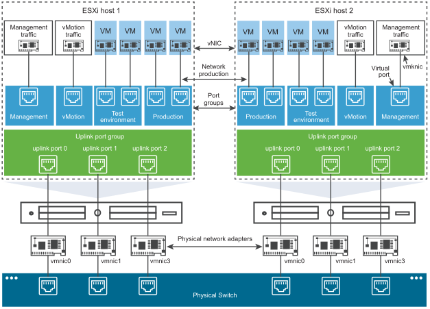
NIC Teaming
NIC teaming occurs when multiple uplink adapters are associated with a single switch to form a team. A team can either share the load of traffic between physical and virtual networks among some or all of its members, or provide passive failover in the event of a hardware failure or a network outage.
VMkernel TCP/IP Networking Layer
The VMkernel networking layer provides connectivity to hosts and handles the standard infrastructure traffic of vSphere vMotion, IP storage, Fault Tolerance, and vSAN.
IP Storage
Any form of storage that uses TCP/IP network communication as its foundation. iSCSI and NFS can be used as virtual machine datastores and for direct mounting of .ISO files, which are presented as CD-ROMs to virtual machines.
TCP Segmentation Offload
TCP Segmentation Offload, TSO, allows a TCP/IP stack to emit large frames (up to 64KB) even though the maximum transmission unit (MTU) of the interface is smaller. The network adapter then separates the large frame into MTU-sized frames and prepends an adjusted copy of the initial TCP/IP headers.
Virtual network Adapters
https://kb.vmware.com/s/article/1001805
When you configure a VM, you can add network adapters (NICs) and specify the adapter type. Whenever possible, select VMXNET3.
Network Adapter Type Description
--------------------------------------------------------------------------
E1000-E1000E    Emulated version of an Intel Gigabit Ethernet NIC, with drivers available in most newer guest operating systems.
VMXNET3         Available only with VMware Tools.
Flexible        Can function as either a Vlance or VMXNET adapter.
SR-IOV pass-through     Allows VM and physical adapter to exchange data without using the VMkernel as an intermediary.
vSphere DirectPath I/O  Allows VM access to physical PCI network functions on platforms with an I/O memory management unit.
PVRDMA          Paravirtualized device that provides improved virtual device performance.
                It provides an RDMA-like interface for vSphere guests.
Single Root I/O Virtualization (SR-IOV)
vSphere supports Single Root I/O Virtualization (SR-IOV). You can use SR-IOV for networking of virtual machines that are latency sensitive or require more CPU resources.
In vSphere, a virtual machine can use an SR-IOV virtual function for networking. The virtual machine and the physical adapter exchange data directly without using the VMkernel as an intermediary. Bypassing the VMkernel for networking reduces latency and improves CPU efficiency.
vSphere VMDirectPath I/O and Dynamic DirectPath I/O
https://kb.vmware.com/s/article/2142307
VMDirectPath I/O (PCI passthrough) enables direct assignment of hardware PCI Functions to virtual machines. This gives the virtual machine access to the PCI Functions with minimal intervention from the ESXi host, potentially improving performance. It is suitable for performance critical workloads such as graphics acceleration for virtual desktops, such as VMware View vDGA, and high data-rate networking such as those found in enterprise class telecommunications equipment. It works particularly well with PCI devices supporting SR-IOV technology, as each virtual function in the device can be assigned to a separate virtual machine.
Paravirtual Remote Direct Memory Access (PVRDMA)
Direct Memory Access (DMA) - A device's capability to access host memory directly, without the intervention of the CPU.
Remote Direct Memory Access (RDMA) - is the ability of accessing memory (read, write) on a remote machine without interrupting the CPU(s) processes on the system.
RDMA Advantages:
1. Zero-copy
    Allows applications to perform data transfers without involving the network software stack.
    Data is sent and received directly to the buffers without being copied between the network layers.
2. Kernel bypass
    Allows applications to perform data transfers directly from the user-space without the kernel involvement.
3. CPU Offload
    Allows applications to access a remote memory without consuming any CPU time on the remote server.
    The remote memory server will be read without any intervention from the remote process (or processor).
    oreover, the cache of the remote CPU will not be filled with the accessed memory content.
How to configure PVRDMA in vSphere
https://docs.mellanox.com/pages/releaseview.action?pageId=15055422
This website provide good detail information about how to configure PVRDMA in vSphere
vSphere Network
A virtual switch has the connection types:
1. VM port group
2. VMkernel port
    It is for ESXi management network, vMotion, IP storage, vSphere Fault Tolerance, vSphere Replication, vSAN
3. Uplink ports
VLAN
VLAN configuration on virtual switches, physical switches, and virtual machines (1003806)
https://kb.vmware.com/s/article/1003806
ESXi support 802.1Q VLAN tagging. VLANs can be configured at the port group level.
There are two types of virtual switches: Standard switch and Distributed Switch.
Network Adapters
vSphere Standard Switch and Standard Port Group

Standard Switch Overview
To provide network connectivity to hosts and virtual machines, you connect the physical NICs of the hosts to uplink ports on the standard switch. Virtual machines have network adapters (vNICs) that you connect to port groups on the standard switch. Every port group can use one or more physical NICs to handle their network traffic. If a port group does not have a physical NIC connected to it, virtual machines on the same port group can only communicate with each other but not with the external network.
Create a vSphere Standard Switch
Standard switch can be created and configured at ESX/ESXi host level
Create a vSphere Standard Switch to provide network connectivity for hosts, virtual machines, and to handle VMkernel traffic.
# Depending on the connection type that you want to create
1. create a new vSphere Standard Switch with a VMkernel network adapter
2. only connect physical network adapters to the new switch
3. create the switch with a virtual machine port group
Procedure
1. In vSphere Client, navigate to the host
2. On the Configure tab, expand Network and select Virtual Switches
3. Click Add networking
4. Select a connection type to use the new standard switch and click Next
    Option                      Description
    ------------------------------------------------------------------------------
    a. VMkernel Network Adapter
            Create a new VMkernel adapter to handle host management traffic, vMotion, network storage, fault tolerance, or vSAN traffic.
    b. Physical Network Adapter
            Add physical network adapters to an existing or a new standard switch.
    c. Virtual Machine Port Group for a Standard Switch
            Create a new port group for virtual machine networking.
5. Select New standard switch and click Next.
6. Add physical network adapters to the new standard switch.
    a. Under Assigned adapters, click Add adapters.
    b. Select one or more physical network adapters from the list and click OK.
        For higher throughput and to provide redundancy, configure at least two physical network adapters in the Active list.
    c. (Optional) Use the Move up and Move down arrows in the Assigned adapters list to change the position of the adapter.
    d. Click Next.
7. If you create the new standard switch with a VMkernel adapter or virtual machine port group, enter connection settings for the adapter or the port group.
    Option                  Description
    i. VMkernel adapter
        a. Enter a label that indicates the traffic type for the VMkernel adapter, for example vMotion.
        b. Set a VLAN ID to identify the VLAN that the network traffic of the VMkernel adapter will use.
        c. Select IPv4, Ipv6 or both.
        d. Select an option from the drop-down menu to set the MTU size. If you select Custom, enter a value for the MTU size.
            You can enable jumbo frames by setting an MTU value greater than 1500. You cannot set an MTU size greater than 9000 bytes.
        e. Select a TCP/IP stack. After you set a TCP/IP stack for the VMkernel adapter, you cannot change it later.
            If you select the vMotion or the Provisioning TCP/IP stack, you will be able to use only this stack to handle vMotion or Provisioning traffic on the host.
        f. If you use the default TCP/IP stack, select from the available services.
        g. Configure IPv4 and IPv6 settings.
    ii. Virtual machine port group
        a. Enter a network Label or the port group, or accept the generated label.
        b. Set the VLAN ID to configure VLAN handling in the port group.
8. On the Ready to Complete page, click Finish.
VMkernel Networking Layer
TCP/IP Stacks at the VMkernel Level
- Default TCP/IP stack
Provides networking support for the management traffic between vCenter Server and ESXi hosts, and for system traffic such as vMotion, IP storage, Fault Tolerance, and so on.
- vMotion TCP/IP stack
Supports the traffic for live migration of virtual machines. Use the vMotion TCP/IP to provide better isolation for the vMotion traffic.
- Provisioning TCP/IP stack
Supports the traffic for virtual machine cold migration, cloning, and snapshot migration. You can use the provisioning TCP/IP to handle Network File Copy (NFC) traffic during long-distance vMotion. NFC provides a file-specific FTP service for vSphere. ESXi uses NFC for copying and moving data between datastores.
- Custom TCP/IP stacks
You can add custom TCP/IP stacks at the VMkernel level to handle networking traffic of custom applications.
Virtual Machines Isolation Testings Network
To test the VMs in an isolated environment, and to prevent connectivity to the external netowrk. We could create a port group, say "Isolated Testing" that does not have any physical NIC connected. All VMs on this "Isolated Testing" port group will be able to communicate with each other, but not with the external network.
Standard Port Groups
Each port group on a standard switch is identified by a network label, which must be unique to the current host. A VLAN ID, which restricts port group traffic to a logical Ethernet segment within the physical network, is optional. For port groups to receive the traffic that the same host sees, but from more than one VLAN, the VLAN ID must be set to VGT (VLAN 4095).
In production deployment, the ESXi host physical uplinks are trunked to the physical switches. It has all the required (multiple) VLANs tagged. We assign the VLAN ID to the port group. The port group are added to the standard switch.
vSphere Distributed Switch and Distributed Port Group
A vSphere Distributed Switch provides centralized management and monitoring of the networking configuration of all hosts that are associated with the switch. You set up a distributed switch on a vCenter Server system, and its settings are propagated to all hosts that are associated with the switch.

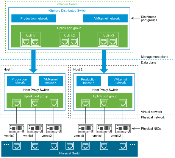
A vSphere Distributed Switch separates the data plane and the management plane. The management functionality of the distributed switch resides on the vCenter Server system that lets you administer the networking configuration of your environment on a data center level. The data plane remains locally on every host that is associated with the distributed switch. The data plane section of the distributed switch is called a host proxy switch. The networking configuration that you create on vCenter Server (the management plane) is automatically pushed down to all host proxy switches (the data plane).
Uplink port group
An uplink port group or dvuplink port group is defined during the creation of the distributed switch and can have one or more uplinks. An uplink is a template that you use to configure physical connections of hosts as well as failover and load balancing policies. You map physical NICs of hosts to uplinks on the distributed switch.
Distributed port group
Distributed port groups provide network connectivity to virtual machines and accommodate VMkernel traffic. You identify each distributed port group by using a network label, which must be unique to the current data center. You configure NIC teaming, failover, load balancing, VLAN, security, traffic shaping , and other policies on distributed port groups.
vSphere ESXi Netwrk Command Lines
esxcli nic list     # List the network interfaces
esxcli nic up -n <vmnic-number>     # Example, esxcli nic up -n vmnic4
Create a Standard Switch with a Virtual Machine Port Group
1. Select the ESXi host from vSphere client
2. Click ADD NETWORKING in the right pane
3. On the Select connect type page, click Virtual Machine Port Group for a standard Switch, and click Next
4. On the Select target device page, click New standard switch, and click Next
5. On the Create a Standard Switch page, click the Add adapters icon (+)
6. Select the required <vmnicx>
        Where <vmnicx> is the uplink that connects to the switch
7. Review the information for the new active adapter and click Next
8. On the Connection setting page, enter <network-name> in the Network label text box, and click Next
9. On the ready to complete page, review the information and click Finish
Create a vSphere Distributed Switch
Create a vSphere distributed switch on a data center to handle the networking configuration of multiple hosts at a time from a central place.
1. In the vSphere Client, right-click a data center from the inventory tree.
2 Select Distributed Switch > New Distributed Switch.
3 On the Name and location page, enter a name for the new distributed switch, or accept the generated name, and click Next.
4. On the Select version page, select a distributed switch version and click Next.
    Option Description
    -------------------------------------------------
    Distributed Switch: 7.0.0 Compatible with ESXi 7.0 and later.
    Distributed Switch: 6.6.0 Compatible with ESXi 6.7 and later.
            Features released with later vSphere distributed switch versions are not supported.
    Distributed Switch: 6.5.0 Compatible with ESXi 6.5 and later.
            Features released with later vSphere distributed switch versions are not supported.
5 On the Configure settings page, configure the distributed switch settings.
    a Use the arrow buttons to select the Number of uplinks.
        Uplink ports connect the distributed switch to physical NICs on associated hosts.
        The number of uplink ports is the maximum number of allowed physical connections to the distributed switch per host.
    b Use the drop-down menu to enable or disable Network I/O Control.
        By using Network I/O Control you can prioritize the access to network resources for certain types of
        infrastructure and workload traffic according to the requirements of your deployment.
    c (Optional) Select the Create a default port group check box to create a new distributed port group with
        default settings for this switch. Enter a Port group name, or accept the generated name.
        If your system has custom port group requirements,
        create distributed port groups that meet those requirements after you add the distributed switch.
    d Click Next.
6 On the Ready to complete page, review the settings you selected and click Finish.
    Use the Back button to edit any settings.
Upgrade a vSphere Distributed Switch to a Later Version
You can upgrade vSphere Distributed Switch version 6.x to a later version. The upgrade lets the distributed switch take advantage of features that are available only in the later version.
Note:
1. To be able to restore the connectivity of the virtual machines and VMkernel adapters if the upgrade fails,
    back up the configuration of the distributed switch.
2. If the upgrade is not successful, to recreate the switch with its port groups and connected hosts,
    you can import the switch configuration file

# Prerequisites
1. Upgrade vCenter Server to version 7.0.
2. Upgrade all hosts connected to the distributed switch to ESXi 7.0.

# Procedure
1. On the vSphere Client Home page, click Networking and navigate to the distributed switch.
2. Right-click the distributed switch and select Upgrade > Upgrade Distributed Switch.
3. Select the vSphere Distributed Switch version that you want to upgrade the switch to and click Next.
4. Review host compatibility and click Next.
    Some ESXi instances that are connected to the distributed switch might be incompatible with the selected target version.
    Upgrade or remove the incompatible hosts, or select another upgrade version for the distributed switch.
5 Complete the upgrade configuration and click Finish.

Caution:
    After you upgrade the vSphere Distributed Switch, you cannot revert it to an earlier
    version. You also cannot add ESXi hosts that are running an earlier version than the new
    version of the switch.
Migrate Network Adapters on a Host to a vSphere Distributed Switch
For hosts associated with a distributed switch, you can migrate network adapters from a standard switch to the distributed switch. You can migrate physical NICs, VMkernel adapters, and virtual machine network adapters at the same time.
To migrate virtual machine network adapters or VMkernel adapters, make sure that the destination distributed port groups have at least one active uplink, and the uplink is connected to a physical NIC on this host. Alternatively, migrate physical NICs, virtual network adapters, and VMkernel adapters at once.
To migrate physical NICs, make sure that the source port groups on the standard switch have at least one physical NIC to handle their traffic. For example, if you migrate a physical NIC that is assigned to a port group for virtual machine networking, make sure that the port group is connected to at least one physical NIC. Otherwise the virtual machines on same VLAN on the standard switch will have connectivity between each other but not to the external network.
Storage and Datastore
Process to Create iSCSI Datastore
Create VMKernel Port Port
# The following steps are used to create a VMKernel Port Group to a Standard Switch
1. Select the ESXi host from vSphere client
2. Select Configure tab, and select VMkernel adapters under Networking
3. Click Add Networking icon
4. On Add Networking window, select VMKernel Netwrok Adapter, and click Next
5. On the Select target device page, click Select an existing standard switch
6. Click Browse, and select the required standard switch <vSwitch0/existing-standardSwwitch>
7. Click OK, and Next
9. On the Port properties page, enter <network-label-name> in the Network label text box, and click Next
10. On the IPv4 settings page, configure the IPv4 settings
    a. Click Use static IPv4 settings
    b. Enter IPv4 address, Subnet mask, default gateway
11. On the Ready to complete page, review and click Finish
Configure iSCSI Adapter on the ESXi host
Use hardware iSCSI adapter in production. Configure software iSCSI adapter if required.
1. Select the ESXi host from vSphere client
2. On the Configure tab under Storage, select Storage Adapters
3. Click Add Software Adapter
4. Confirm that Add Software iSCSI adapter is selected and click OK
5. In the Software Adapters list, select the newly created iSCSI software adapter
6. Select the Properties tab
7. Veify the adapter status as Enabled
8. Verify the iSCSI name matches iqn.<depends-on-confiured-value>
Connect the iSCSI Software Adapters to Storage
1. Select the ESXi host from vSphere client
2. On the Configure tab under Storage, select Storage Adapters
3. Select the iSCSI adapter, and navigate to Dynamic Discovery tab, then click Add
4. In the Add Send Target Server window, enter <target-iscsi-IP-address> in the iSCSI Server text box and click OK
    Note: A warning appears to recommend rescan.
          DO NOT rescan yet
5. In the Storage Adapters pane, click the Network Port Binding tab
6. Click Add
7. Select the <iSCSI-adapter-name>, and click OK
8. Click Rescan Storage
9. Click OK, keep default to scan new storage devices, and new VMFS volumes
Create VMFS Datastore for the ESXi Host using the iSCSI storage
1. From vSphere client, from the Menu drop down menu, select Storage
2. Navigate to the required <datacenter>, right click and select Storage -> New Datastore
3. On the Type page, select VMFS and click Next
4. On the Name and device selection page, enter <datastore-name> in the Datastore name text box
5. From the Select a host to view its accessible disks/LUN drop down menu, select <required-esxi-host>
    Note:   The LUN list appears, select the <required-LUN-number>
6. Click Next
7. On the VMFS version page, accept VMFS 6 and click Next
8. On the Partition configuration page, set the size or select default (Use all available partitions)
9. On the Ready to complete page, review the information and click Finish
Process to Expand the VMFS Datastore
1. From vSphere client, in Storage view, select the required VMFS datastore
2. View properties, such as Backing devices for information
3. On the select Device page, select the required <LUN number>
4. Select the size or use all the available partitions, click Next
5. on the Ready to complete page, review the information and click Finish
Configuring vSwitch or vNetwork Distributed Switch from commmand line
https://kb.vmware.com/s/article/1008127
This article provides commands and information to restore management network connectivity via the correct vmnic interface.
# To restore the Management vmkernel interface to the correct vmnic interface:
1. View the current vSwitch configuration and vmkernel interface configuration using these commands:
    esxcli network vswitch standard list # list current vswitch configuration
    esxcli network vswitch dvs vmware list # list Distributed Switch configuration
    esxcli network ip interface list # list vmkernel interfaces and their configuration
    esxcli network nic list # display listing of physical adapters and their link state
2. Add or remove network cards (known as vmnics) to or from a Standard vSwitch using these commands:
    esxcli network vswitch standard uplink remove --uplink-name=vmnic --vswitch-name=vSwitch # unlink an uplink
    esxcli network vswitch standard uplink add --uplink-name=vmnic --vswitch-name=vSwitch # add an uplink
3. Add or remove network cards (known as vmnics) to or from a vNetwork Distributed Switch (vDS) using these commands:
    esxcfg-vswitch -Q vmnic -V dvPort_ID_of_vmnic dvSwitch # unlink/remove a vDS uplink
    esxcfg-vswitch -P vmnic -V unused_dvPort_ID dvSwitch # add a vDS uplink
Note:
    If connectivity was lost when migrating management networking to a Distributed Switch,
    it may be necessary to remove or disable the existing management vmkernel interface and
    recreate it in a Standard vSwitch port group with the same IP configuration.
4. On a vSphere Distributed Switch (vDS), delete an existing VMkernel port using this command:
    esxcli network ip interface remove --interface-name=vmkX
Note:
    The vmk interface number used for management can be determined by running the esxcli network ip interface list command.
    After the unreachable vmkernel port has been removed, it can be recreated on a Standard Switch.
5. If an existing Standard Switch does not exist, you can create a new one as well as a port-group to use with these commands:
    esxcli network vswitch standard add --vswitch-name=vSwitch
    esxcli network vswitch standard portgroup add --portgroup-name=portgroup --vswitch-name=vSwitch
Note:
    When creating a virtual switch, there are no linked vmnics by default.
    You will need to link vmnics as described earlier in this article.
6. To create a VMkernel port and attach it to a portgroup on a Standard vSwitch, run these commands:
    esxcli network ip interface add --interface-name=vmkX --portgroup-name=portgroup
    esxcli network ip interface ipv4 set --interface-name=vmkX --ipv4=ipaddress --netmask=netmask --type=static
Note:
    By default, the ESXi, the management vmkernel port is vmk0 and resides in a Standard Switch portgroup called Management Network.
7. If the vmnics associated with the management network are VLAN trunks, you may need to specify a VLAN ID for the management portgroup.
   To set or correct the VLAN ID required for management connectivity on a Standard vSwitch, run this command:
    esxcli network vswitch standard portgroup set -p portgroup --vlan-id VLAN
8. It may be necessary to restart the host's management agents if network connectivity is not restored despite a correct configuration:
    services.sh restart
    ./sbin/services.sh restart
ESXi - Migrate from a Standard Switch to a Distributed Switch
https://portal.nutanix.com/page/documents/kbs/details?targetId=kA032000000bmqQCAQ
There are two types of virtual switches (vswitch) in vSphere:
vSphere Standard Switch
vSphere Distributed Switch
They all share the following common features:
1. Layer 2 switc
2. VLAN segmentation (802.1Q tagging)
3. IPv6 suppor
3. NIC teaming
4. Outbound traffic shaping
5. Cicso Discovery Protocol (CDP)
The following featurs are only available in distributed switches
1. Inbound traffic shaping
2. Load-based teaming
3. Data center level management
4. NetFlow
5. Port mirroring
6. Access to NSX-T port groups
7. Link Layer Discovery Protocol (LLDP)
Security Policy for a standard switch and distributed switch
The network security policy contains the following configurations
- Promiscuous mode: Promiscuous mode allows a virtual switch or port group to forward all traffic regardless of their destinations. The default is Reject.
- MAC address changes: If this option is set to Reject and the guest attempts to change the MAC address assigned to the virtual NIC, it stops receiving frames.
- Forged transmits: A frame’s source address field might be altered by the guest and contain a MAC address other than the assigned virtual NIC MAC address. You can set the Forged Transmits parameter to accept or reject such frame
NIC teaming and failover policies
Load balancing policies
Load-balancing policy
    1. originating virtual port ID
    2. source MAC hash
    3. source and destination IP hash
        Requires 802.3ad Link Aggregation Control Protocl (LADP) or EtherChannel support on physical switch
Failback policy
Notify switches policy
EtherChannel
https://www.section.io/engineering-education/etherchannel-technology/
EtherChannel Technology is a link aggregation technology that makes it possible to combine several physical links between switches into one logical link to provide high-speed links and redundancy without being blocked by the Spanning Tree Protocol.
There is a provision of fault tolerance, load balancing, increased bandwidth, and redundancy. Formed through negotiation with two protocols: Port Aggregation Protocol (PAgp) and Link Aggregation Control Protocol (LACP).
Detecting and Handling Network Failure
The VMkernel can use link status or beaconing, or both, to detect a network failure.
Migrate VMkernels and Physical NICS to a vSphere Distributed Switch
Manually migrate VMkernel adapters from a vSphere Standard Switch or from an N-VDS switch to a vSphere Distributed Switch.
Note: Starting with NSX-T Data Center 3.0, transport nodes can be created using vSphere Distributed Switch.
After preparing the transport node with vSphere Distributed Switch host switch type (referred to as an NSX Switch in vCenter Server), manually migrate VMkernel adapters (vmks) and physical NICs (vmnics) to an NSX Switch on the ESXi host.
In the procedure below, consider this switch configuration:
- vmk0, vmk1 are connected to vSwitch0, and vmnic0, vmnic1 are configured as uplink 1 and 2 respectively on the vSwitch0.
- NSX Switch does not have any vmnic or VMkernel adapter configured.
At the end of the procedure, vmnic0, vmnic1 and vmk0, vmk1 are migrated to vSphere Distributed Switch (referred to as an NSX Switch in vCenter Server).
Prerequisites
- ESXi hosts are prepared as transport nodes using vSphere Distributed Switch.
Procedure
1. From a browser, log in with admin privileges to a vCenter Server at https://<vCenterServer-ip-address>.
2. Navigate to Host → Configure → Virtual Switches.
3. View existing vmknics configured on vSwitch0.
4. Make a note of the vmknics to be migrated to the distributed virtual port group of the NSX Switch.
5. Navigate to Home → Networking, to view all switches configured in the data center.
6. In the Switch page, click Actions → Add and Manage Hosts.
7. Select Manage Host Networking.
8. Click Next.
9. In the Select Member Hosts window, select hosts.
10. Click Ok.
11. In the Manage physical adapters window, claim unassigned adapters, as there are available vmnics that can be attached to a switch.
    a. Select an unclaimed uplink and click Assign uplink.
    b. Map a vmnic to an uplink on the NSX Switch.
    c. Click Ok.
12. In the Manage VMkernel adapters window, assign port groups to NSX Switch.
    a. Select a vmk on vSwitch0 and click Assign port group.
    b. Select a NSX port group to assign a vmk to an NSX segment.
    c. Perform steps a and b for the remaining hosts that are managed by the switch.
13. Finish the Add and Manage Hosts wizard.
14. To verify vmk0 and pnics are migrated from vSwitch0 to NSX Switch on the ESXi host, navigate to Host → Configure → Virtual Switches.
    View the updated switch configuration.
15. Alternatively, run the API command, https://<NSXManager-IP-address>/api/v1/logical-ports, to verify migration of VMkernel adapters is successful.

Note:
All vmk0 ports are set to Unblocked VLAN state because management traffic and services are managed by vmk0 ports.
These vmk0 ports in Unblocked VLAN state allows admins to connect to the vmk0 port if hosts lose connectivity.
vSphere Customs Tags for inventory objectss
https://williamlam.com/2015/01/custom-attributes-vsphere-tags.html
https://blogs.vmware.com/vsphere/2020/08/vsphere-tags-and-custom-attributes.html
A tag is a label that you can apply to objects in the vSphere inventory. When you create a tag, you assign that tag to a category. Categories allow you to group related tags together. When you define a category, you can specify the object types for its tags, and whether more than one tag in the category can be applied to an object.
Tags help make these objects more sortable. You can associate a set of objects of the same type by searching for objectives by a given tag.
You can use tags to group and manage VMs, clusters, and datastores, for example:
- Tag VMs that run production workloads
- Tag VMs based on their guest operating system.
The category is a broader construct and is basically a collection of related tags.
A Category can be defined so that it can accommodate more than one tag. After creating a category, it can be associated to a corresponding vSphere inventory object viz. “Folder”, “Host”, “Virtual Machines” etc.
Virtual Storage
https://storagehub.vmware.com/
vSphere traditional storage models

vSphere software defined storage models

ESXi hosts support the storage technologies, such as
Direct-attached storage
    Internal or external storage disks or arrays attached to the host through a direct connection instead of a network connection
Fibre Channel (FC)
    A high-speed transport protocol used for SANs, Fibre Channel node is a server, a storage system,
Fiber Channel over Ethernet (FCoE)
    The Fibre Channel traffic is encapsulated into Fibre Channel over Ethernet (FCoE) frames
iSCSI
    A SCSI transport protocol, providing access to storage devices and cabling over standard TCP/IP networks
NAS
    Storage shared over standard TCP/IP networks at the file system level.
vSphere Storage Protocol and Storage Support
vSphere supports and uses the following storage protocol, datastore type and support features:
Datastore Type  Storage Protocol    Boot from    vSphere    vSphere  vSphere
                                    SAN          vMotion       HA       DRS
-----------------------------------------------------------------------------
                Fibre Channe            Y           Y           Y       Y
VMFS            FCoE                    Y           Y           Y       Y
                iSCSI                   Y           Y           Y       Y
                iSER/NVMe-oF (RDMA)     N           Y           Y       Y
                DAS (SAS, SATA, NVMe)   N/A         Y           Y       Y
-----------------------------------------------------------------------------
NFS             NFS                     N           Y           Y       Y
-----------------------------------------------------------------------------
vSphere Virtual FC/Ethernet             N           Y           Y       Y
Volumes         (iSCSI, NFS)
-----------------------------------------------------------------------------
vSAN Datastore  vSAN                    N           Y           Y       Y
VMFS Support
The native vSphere Virtual Machine File System (VMFS) format. It is a special high-performance file system format that is optimized for storing virtual machines.
ESXi hosts support VMFS5 and VMFS6
a. Concurrent access to shared storage
b. Dynamic expansion
c. On-disk locking

Features supported by VMFS6
a. 4K native storage devices
b. Automatic space reclamation
VMFS Metadata Updates
A VMFS datastore holds virtual machine files, directories, symbolic links, RDM descriptor files, and so on. The datastore also maintains a consistent view of all the mapping information for these objects. This mapping information is called metadata.
Metadata is updated each time you perform datastore or virtual machine management operations. Examples of operations requiring metadata updates include the following:
Creating, growing, or locking a virtual machine file
Changing attributes of a file
Powering a virtual machine on or off
Creating or deleting a VMFS datastore
Expanding a VMFS datastore
Creating a template
Deploying a virtual machine from a template
Migrating a virtual machine with vMotion
When metadata changes are made in a shared storage environment, VMFS uses special locking mechanisms to protect its data and prevent multiple hosts from concurrently writing to the metadata.
Snapshot Formats on VMFS
When you take a snapshot, the state of the virtual disk is preserved, which prevents the guest operating system from writing to it. A delta or child disk is created. On the VMFS datastore, the delta disk is a sparse disk.
Depending on the type of your datastore, delta disks use different sparse formats.
Snapshot Formats    VMFS5                                   VMFS6
VMFSsparse          For virtual disks smaller than 2 TB.    N/A
SEsparse            For virtual disks larger than 2 TB.     For all disks.
A virtual disk stored on a VMFS datastore always appears to the VM as a mounted SCSI device.
NFS
Best Practices VMware vSphere on NFS
If you plan to use Kerberos authentication with the NFS 4.1 datastore, make sure to configure the ESXi hosts for Kerberos authentication.
NFS datastores are treated like VMFS datastores because they can hold VM files, templates, and ISO images.
# Create NFS datastore Procedure
1. In the vSphere Client object navigator, browse to a host, a cluster, or a data center.
2. From the right-click menu, select Storage > New Datastore.
3. Select NFS as the datastore type and specify an NFS version.
    NFS 3
    NFS 4.1
Important:
    If multiple hosts access the same datastore, you must use the same protocol on all hosts.
4. Enter the datastore parameters.
    Option          Description
    -------------------------------------------------
    Datastore name  The system enforces a 42 character limit for the datastore name.
    Folder          The mount point folder name
    Server          The server name or IP address. You can use IPv6 or IPv4 formats.
                    With NFS 4.1, you can add multiple IP addresses or server names if the NFS server supports trunking.
                    The ESXi host uses these values to achieve multipathing to the NFS server mount point.
5. Select Mount NFS read only if the volume is exported as read-only by the NFS server.
6. To use Kerberos security with NFS 4.1, enable Kerberos and select an appropriate Kerberos model.
    Option                    Description
    ------------------------------------------------------
    Use Kerberos for authentication only (krb5)
                        Supports identity verification
    Use Kerberos for authentication and data integrity (krb5i)
                        In addition to identity verification, provides data integrity services.
                        These services help to protect the NFS traffic from tampering by checking data packets for any potential modifications.
    Note:
        If you do not enable Kerberos, the datastore uses the default AUTH_SYS security.
7. If you are creating a datastore at the data center or cluster level, select hosts that mount the datastore.
8. Review the configuration options and click Finish.
vSAN
vSAN is hypervisor-converged, software-defined storage for virtual environments that does not use traditional external storage.
By clustering host-attached hard disk drives (HDDs) or solid-state drives (SSDs), vSAN creates an aggregated datastore shared by VMs.
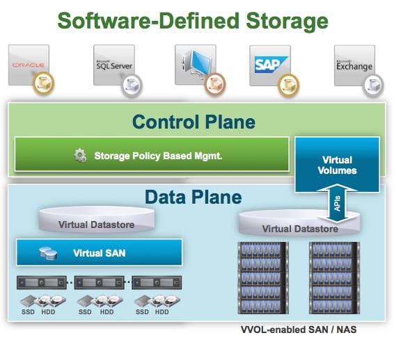
vSphere Virtual Volumes (vVols)
https://www.vmware.com/au/products/vsphere/virtual-volumes.html
https://kb.vmware.com/s/article/2113013
vVols virtualizes SAN/NAS arrays, enabling a more efficient operational model optimized for virtualized environments and centered on the application instead of the infrastructure.
vVols uniquely shares a common storage operational model with vSAN, the market leading hyperconverged infrastructure (HCI) solution. Both solutions use storage policy-based management (SPBM) to eliminate storage provisioning, and use descriptive policies at the VM or VMDK level that can be applied or changed in minutes. SPBM accelerates storage operations and reduces the need for specialized skills for storage infrastructure.
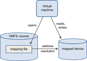
Raw Device Mapping
An RDM is a mapping file in a separate VMFS volume that acts as a proxy for a raw physical storage device. With the RDM, a virtual machine can access and use the storage device directly. The RDM contains metadata for managing and redirecting disk access to the physical device.
The file gives you some of the advantages of direct access to a physical device, but keeps some advantages of a virtual disk in VMFS. As a result, it merges the VMFS manageability with the raw device access.

Fibre Channel Storage
ESXi supports the following Fibre Channel SAN
- 32 Gbps Fibre Channel
- Fibre Channel over Ethernet (FCoE)
To connect to the Fibre Channel SAN, your host should be equipped with Fibre Channel host bus adapters (HBAs)
You can access the LUNs and create datastores for your storage needs. These datastores use the VMFS format.
Alternatively, you can access a storage array that supports vSphere Virtual Volumes and create vSphere Virtual Volumes datastores on the array’s storage containers.
Each node in the SAN has one or more ports that connect it to the SAN. Ports can be identified by
World Wide Port Name (WWPN)
    The Fibre Channel switches discover the WWPN of a device or host and assign a port address to the device.
Port_ID
    The Fibre Channel switches assign the port ID when the device or host logs in to the fabric.
    The port ID is valid only while the device is logged on.
We can protect access to storage in the vSphere environment by using zoning and LUN masking with the SAN resources.
Multipathing with Fibre Channel
Multipathing is having more than one path from a host to a LUN.
By default, ESXi hosts use only one path from a host to a given LUN at any one time. If the path actively being used by the ESXi host fails, the server selects another available path.
The process of detecting a failed path and switching to another is called path failover. A path fails if any of the components along the path (HBA, cable, switch port, or storage processor) fail.
Fibre Channel over Ethernet
ESXi host contains FCoE adapters to connect to the shared Fibre Channel devices by using an Ethernet network.
# Process to Configure ESXi host for FCoE
1. Install physical FCoE NICs in the ESXi host
2. Connect the VMkernel to the physical FCoE NICs in ESXi host
    Note: ESXi host support maximum of 4 network adapters for software FCoE
3. During the FCoE initialization, ESXi host discovers the VLAN ID and priority class

# Procedure
1. Select the ESXi host from vSphere client
2. Navigate to Configure -> Storage -> Storage Adapters
3. Click Add Software Adapter
4. Select Add Software FCoE Adapter
    a. Select physical network adapter, such as vmnic1
    b. Select VLAN ID
    c. Select Prority Class
    d. Select Controller MAC Address
5. Click OK
iSCI Storage
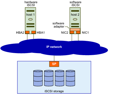
With iSCSI, SCSI storage commands that your virtual machine issues to its virtual disk are converted into TCP/IP protocol packets and transmitted to a remote device, or target, on which the virtual disk is located. To the virtual machine, the device appears as a locally attached SCSI drive.
To access remote targets, the ESXi host uses iSCSI initiators. Initiators transport SCSI requests and responses between ESXi and the target storage device on the IP network. ESXi supports these types of initiators:
- Software iSCSI adapter. VMware code built into the VMkernel. Allows an ESXi host to connect to the iSCSI storage device through standard network adapters. The software initiator handles iSCSI processing while communicating with the network adapter.
- Hardware iSCSI adapter. Offloads all iSCSI and network processing from your host. Hardware iSCSI adapters are broken into two types.
a. Dependent hardware iSCSI adapter, known as iSCSI host bus adapter. Leverages the VMware iSCSI management and configuration interfaces.
b. Independent hardware iSCSI adapter. Leverages its own iSCSI management and configuration interfaces.
You must configure iSCSI initiators for the host to access and display iSCSI storage devices.
iSCSI Storage depicts hosts that use different types of iSCSI initiators.
- The host on the left uses an independent hardware iSCSI adapter to connect to the iSCSI storage system.
- The host on the right uses software iSCSI.
Dependent hardware iSCSI can be implemented in different ways and is not shown. iSCSI storage devices from the storage system become available to the host. You can access the storage devices and create VMFS datastores for your storage needs.

Discovery Sessions
A discovery session is part of the iSCSI protocol. The discovery session returns the set of targets that you can access on an iSCSI storage system. ESXi systems support dynamic and static discovery.
- Dynamic discovery. Also known as Send Targets discovery. Each time the ESXi host contacts a specified iSCSI storage server, it sends a Send Targets request to the server. In response, the iSCSI storage server supplies a list of available targets to the ESXi host. Monitor and manage with commands
esxcli iscsi adapter discovery sendtarget
vicfg-iscsi
- Static discovery. The ESXi host does not have to perform discovery. Instead, the ESXi host uses the IP addresses or domain names and iSCSI target names (IQN or EUI format names) to communicate with the iSCSI target. Monitor and manage with commands
esxcli iscsi adapter discovery statictarget
vicfg-iscsi
For either case, you set up target discovery addresses so that the initiator can determine which storage resource on the network is available for access. You can do this setup with dynamic discovery or static discovery. With dynamic discovery, all targets associated with an IP address or host name and the iSCSI name are discovered. With static discovery, you must specify the IP address or host name and the iSCSI name of the target you want to access. The iSCSI HBA must be in the same VLAN as both ports of the iSCSI array.
Discovery Target Names
The target name is either an IQN name or an EUI name.
- The IQN name uses the following format:
iqn.yyyy-mm.{reversed domain name}:id_string
For example:
    iqn.2007-05.com.mydomain:storage.tape.sys3.abc
The ESXi host generates an IQN name for software iSCSI and dependent hardware iSCSI adapters. You can change that default IQN name. 2. he EUI name is described in IETF rfc3720 as follows:
a. The IEEE Registration Authority provides a service for assigning globally unique identifiers EUI. The EUI-64 format is used to build a global identifier in other network protocols. For example, Fibre Channel defines a method of encoding it into a WorldWideName.
The format is eui. followed by an EUI-64 identifier (16 ASCII-encoded hexadecimal digits).
For example:
    eui.02004567A425678D
The IEEE EUI-64 iSCSI name format can be used when a manufacturer is registered with the IEEE Registration Authority and uses EUI-64 formatted worldwide unique names for its products.
Check in the UI of the storage array whether an array uses an IQN name or an EUI name.
Storage device are identied in storage adapter, under Paths tab.
1. Runtime name: Uses the vmhbaN:C:T:L convention. This name is not persistent through reboots.
    N   starts from 65
    Cx  starts from C0
    Tx  starts from T0
    Lx  starts from L0
2. Target: Identifies the iSCSI target address and port.
    Either iqn or eui name
3. LUN: A unique identifier designated to individual or collections of hard disk devices.
    x   digit identifier
ESXi network configuration for IP storage
A VMkernel port must be created for ESXi to access software iSCSI. The same port can be used to access NAS and NFS storage.
To optimize your vSphere networking setup, you separate iSCSI networks from NAS and NFS networks
Physical separation is preferred
If physical separation is not possible, use VLANs
software iSCSI
creating a VMkernel port on a virtual switch to handle your iSCSI traffic.
# Procedure
1. Select the host and click the Configure tab
2. Select Storage Adapters and click Add Software Adapter

Note: only one software iSCSI adapter can be activated.
iSCSI Security - CHAP
iSCSI initiators use CHAP for authentication.
# Configure CHAP
1. Select the host and click the Configure tab
2. Select the Storage Adapter, and select the iSCSI adapter
3. On Properties tab, under Authentication section, click Edit
4. Select
    a. Use unidrectional CHAP, or
    b. Use bidirectional CHAP
Overcommitted Datastores
A datastore becomes overcommitted when the total provisioned space of thin-provisioned disks is greater than the size of the datastore.
To increase the size of the VMFS datastore
1. Perform a rescan to ensure that all hosts see the most current storage
2. Record the unique identifier of the volume that will be expanded
3. Use one of the following methods:
    a. add an extent to the VMFS datastore. An extent is a partition on a LUN
    b. expand the VMFS datastore. The underlying extent has been extended.
Datastore Maintenance Mode and Operations
# Procedure
1. migrate all VMs and templates to a different datastore. These include power on VMS, and power off VMs
2. place the datastore in maintenance mode

# Steps
1. In vSphere client, locate the datastore
2. Right click and select Maintenance Mode -> Enter Maintenance Mode
When select
    Let me migrate storage for all virtual machines and continue entering maintenance mode after migration check box
    all VMs and templates on the datastore are automatically migrated to the datastore of your choice.
Datastore maintenance mode is a function of the vSphere Storage DRS feature.
Datastore Operations
# To unmount the datastore
1. Select the datastore
2. Right click and select Unmount Datastore
    Note:
    a. An unmounted datastore remains intact but cannot be seen from the hosts that have been unmounted
    b. It continues to appear on other hosts, where it remains mounted

# To delete the datastore
1. Select the datastore
2. Right click and select Delete Datastore
    Note: The deleted datastore permanently removes all files on the datastore
Before unmounting a VMFS datastore, use the vSphere Client to verify the following conditions:
1. No virtual machines reside on the datastore.
2. The datastore is not part of a datastore cluster.
3. The datastore is not managed by vSphere Storage DRS.
4. vSphere Storage I/O Control is deactivated.
5. The datastore is not used for vSphere HA heartbeat.

Note
    To keep data, back up the contents of the VMFS datastore before deleting the datastore.
Storage Array Multipathing
Arrays provide active-active and active-passive storage processors. Multipathing algorithms interact with these storage arrays:
- vSphere offers native path selection, load-balancing, and failover mechanisms.
- Third-party vendors can create software for ESXi hosts to properly interact with the storage arrays
VMware path selection policies include:
# Scalability
    Round Robin
# Availability
    a. Most Recently Used (MRU)
    b. Fixed Third-party

# How to configure multipathing
1. Select the datastore
2. Select Configure tab
3. Navigate to Multipathing Policies, and click Edit Multiplathing
4. Select
    a. Most Recently Used
    b. Roubnd Robin
        Check with storage team for storage support before enabling it
    c. Fixed
        This policy is the default policy for active-active storage device
        If the host cannot access the disk through the preferred path, it tries the alternative paths.
NFS Datastore
An NFS file system is on a NAS device that is called the NFS server.
The NFS server contains one or more directories that are shared with the ESXi host over a TCP/IP network. An ESXi host accesses the NFS server through a VMkernel port that is defined on a virtual switch
An NFS datastore can be created as either NFS 3 or NFS 4.1.
NFS 3                                           NFS 4.1
ESXi managed multipathing                       Native multipathing and session trunking
AUTH_SYS (root) authentication                  Optional Kerberos authentication
VMware proprietary client-side file locking     Server-side file locking
Client-side error tracking                      Server-side error tracking
Configuration Considerations
Compatibility issues between the two NFS versions prevent access to datastores using both protocols at the same time from different hosts. If a datastore is configured as NFS 4.1, all hosts that access that datastore must mount the share as NFS 4.1. Data corruption can occur if hosts access a datastore with the wrong NFS version.
NFS 4.1 does not support
a. vSphere Storage DRS and Storage I/O Control
b. Site Recovery Manager
Procedure to configure NFS datastores
1. Create a VMkernel port
    a VMkernel port must be configured on a virtual switch
    For better performance and security, separate your NFS network from the iSCSI network.
2. Create the NFS datastore by providing the following information
    a. NFS version: 3 or 4.1
    b. Datastore name
    c. NFS server names or IP addresses
    d. Folder on the NFS server, for example, /templates or /nfs_share
    e. Hosts that mount the datastore
    f. Whether to mount the NFS file system as read only
    g. Authentication parameters
Configure NFS Kerberos Authentication
We need to add each ESXi host to the Active Directory domain, then configure NFS Kerberos credentials. The NFS server joins the Active Directory domain.
To use NFS Kerberos
1. Use only one NFS version
    NFS 3 and 4.1 use different authentication credentials, resulting in incompatible UID and GID on files.
2. Use the same Active Directory service account
    Using different Active Directory users on different hosts that access the same NFS share can cause the vSphere vMotion migration to fail.
3. Use host profiles (preferred)
    NFS Kerberos configuration can be automated by using host profiles to reduce configuration conflicts.
4. Use same NTP servers
    Time must be synchronized between all participating components
How to join ESXi host to Active Directory domain
1. In vSphere client, select the ESXi host
2. Select Configure tab -> Authentication Services
3. Select JOIN DOMAIN

To configure NFS Kerberos Credentials
4. Navigate to NFS kerberos Credentials
5. Click Edit, and enter the service account credential
Create NFS datastore and use Kerberos
1. In vSphere client, select the location to create the NFS datasore, such as Datacenter, cluster
2. Right click and select New Datastore
3. Select NFS type, and NFS version
4. Enter Name, and configuration
5. In Configure Kerberos Authentication, select option
    a. Kerberos5 authentication
    b. Kerberos5i authentication and data integrity
Configuring multipathing for NFS 4.1
NFS 4.1 supports native multipathing and session trunking. To configure multipathing, enter multiple server IP addresses when configuring the datastore.
# Configure multipathing for NFS 4.1
1. Edit the existing NFS datastore, or create new NFS datastore
2. Select NFS versoin - NFS 4.1
3. In Name and Configuration section
    a. Datastore Name:  <Enter datastore name>
    b. Folder:  /<NFS folder path>
    c. Server: add multiple IP addresses
4. Configure Kerberso authentication
5. Host accessibility:
vSAN
A vSAN cluster requires
- A minimum of three hosts to be part of the vSphere cluster and configured for vSAN
- A vSAN network
- Local disks on each host that are pooled to create a virtual shared vSAN datastor
A vSAN cluster stores and manages data as flexible data containers called objects. When you provision a VM on a vSAN datastore, a set of objects is created:
- VM home namespace: Stores the virtual machine metadata (configuration files)
- VMDK: Virtual machine disk
- VM swap: Virtual machine swap file, which is created when the VM is powered on
- VM memory: Virtual machine’s memory state when a VM is suspended or when a snapshot is taken of a VM and its memory state is preserved
- Snapshot delta: Created when a virtual machine snapshot is taken
Virtual Machine Management
managing virtual machines and includes the following information:
1. Creating and deploying virtual machines, templates, and clones
2. Deploying OVF templates
3. Using content libraries to manage templates and other library items
4. Configuring virtual machine hardware and virtual machine options
5. Managing multi-tiered applications with VMware vSphere vApp
6. Monitoring solutions with the vCenter Solutions Manager
7. Managing virtual machines, including using snapshots
8. Upgrading virtual machines
VM Customization Specifications
You can create a customization specification to prepare the guest operating system:
- Specifications are stored in the vCenter Server database.
- Windows and Linux guests are supported
# To create or manage VM Customization Specifications
1. From vSphere client, select Policies and Profiles
2. Select VM Customization Specifications
3. click New
    To create new Customization Specifications
or select existing Customization Specifications, and click Edit
During cloning or deploying new virtual machine, use the defined customization settings.
1. VMware Tools must be installed on the guest operating system that you want to customize.
2. The guest operating system must be installed on a disk attached to SCSI node 0:0 in the VM configuration.
Instant Clone
https://williamlam.com/2018/04/new-instant-clone-architecture-in-vsphere-6-7-part-1.html
https://williamlam.com/2018/04/new-instant-clone-architecture-in-vsphere-6-7-part-2.html
Use Instant Clone Technology to create a powered-on VM from the running state of another powered-on VM:
- The processor state, virtual device state, memory state, and disk state of the destination (child) VM are identical to the states of the source (parent) VM.
- Snapshot-based disk sharing is used to provide storage efficiency and to improve the speed of the cloning process.
While the source VM is stunned, a new writable delta disk is generated for each virtual disk, and a checkpoint is taken and transferred to the destination VM. The destination VM powers on by using the source’s checkpoint. After the destination VM is fully powered on, the source VM resumes running.
Instant clone VMs are fully independent vCenter Server inventory objects. You can manage instant clone VMs like regular VMs, without any restriction
The new version of Instant Clone also known as a "Parentless" Instant Clone, the instantiated VM no longer depends on the SourceVM. Once instantiated, the Instant Clone is an independent VM that starts executing from the exact running state of the sourceVM.
Lastly, you can now create an Instant Clone from either a running or a frozen SourceVM. In the past, you had to "freeze" the SourceVM which meant it was no longer accessible as part of the Instant Clone creation workflow.

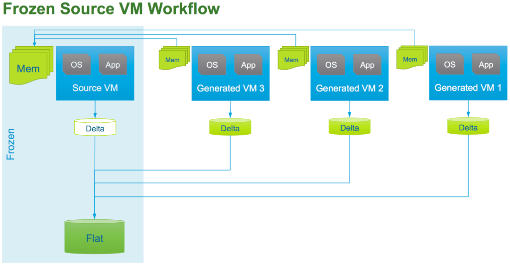
Content Library
Content libraries are repositories of OVF templates and other file types that can be shared and synchronized across vCenter Server systems in different data centers.
Using content libraries, administrators can perform the following functions:
- Store, version, and share content.
- Perform distributed file management.
- Synchronize content libraries across sites and vCenter Server instances.
- Mount an ISO file directly from a content library.
- Perform live updates of VM template
Library items include VM templates, vApp templates, or other VMware objects that can be contained in a content library.
# Process
1. In vSphere client, navigate to the VM template, then right click
2. Select "Clone to Library"

or Navigate to the VM, then right click, and select Clone as Template to Library
Modifying virtual machine settings
vSphere 7.0 makes the following virtual devices available: •
- Watchdog timer: Virtual device used to detect and recover from operating system problems. If a failure occurs, the watchdog timer attempts to reset or power off the VM. This feature is based on Microsoft specifications - Watchdog Resource Table (WDRT) and Watchdog Action Table (WDAT).
The watchdog timer is useful with high availability solutions such as Red Hat High Availability and the MS SQL failover cluster. This device is also useful on VMware Cloud and in hosted environments for implementing custom failover logic to reset or power off VMs.
- Precision Clock: Virtual device that presents the ESXi host's system time to the guest OS. Precision Clock helps the guest operating system achieve clock accuracy in the 1 millisecond range.
- Virtual SGX: Virtual device that exposes Intel's SGX technology to VMs. Intel’s SGX technology prevents unauthorized programs or processes from accessing certain regions in memory. Intel SGX meets the needs of the Trusted Computing Industry.
Inflating Thin-Provisioned Disk
Thin-provisioned virtual disks can be converted to a thick, eager-zeroed format. To inflate a thin-provisioned disk: • The VM must be powered off. • Right-click the VM’s file with the .vmdk extension and select Inflate.
VM Options - VM Boot Setting
When you build a VM and select a guest operating system, BIOS or EFI (Extensible Firmware Interface) is selected automatically, depending on the firmware supported by the operating system. If the operating system supports BIOS and EFI, you can change the boot option as needed. However, you must change the option before installing the guest OS.
UEFI Secure Boot is a security standard that helps ensure that your PC boots use only software that is trusted by the PC manufacturer. In an OS that supports UEFI Secure Boot, each piece of boot software is signed, including the bootloader, the operating system kernel, and operating system drivers. If you configure Secure Boot for a VM, you can load only signed drivers into that VM
vSphere vMotion
A vSphere vMotion migration moves a powered-on VM from one host to another. vSphere vMotion changes the compute resource only. vSphere vMotion provides the following capabilities:
- Improvement in overall hardware use
- Continuous VM operation while accommodating scheduled hardware downtime
- vSphere DRS to balance VMs across hosts
vSphere vMotion does not move VM storage.
vSphere vMotion Enhancements
The enhancements to vSphere vMotion result in a more efficient live migration and a reduction in stun time for VMs. The vSphere vMotion enhancements in vSphere 7 are as follows:
- Only one virtual CPU is claimed for page tracer, reducing the performance impact during memory precopy.
- The virtual machine monitor (VMM) process sets the read-only flag on 1 GB pages.
- During stun operations, a compacted memory bitmap is transferred to the destination.
- The stun times for VMs are reduced.
In earlier vSphere versions, the page tracers are installed on all the virtual CPUs, which can impact the VMs workload performance.
In vSphere 7, one virtual CPU is claimed for all page installing and page firing (memory page is overwritten by the guest), rather than having all the virtual CPUs doing this tracking.
One virtual CPU sets all page table entries (PTE) in global memory to read-only and manages the page tracer installer and page firing.
All virtual CPUs must still flush the translation lookaside buffer (TLB), but this task is now done at different times to reduce performance impact. Having only one virtual CPU to manage the PTE frees the remaining virtual CPUs to manage the VMs' workload.
As of vSphere 7, the virtual machine monitor (VMM) process sets the read-only flag on 1 GB pages. If a page fire (a memory page is overwritten) occurs, the 1 GB PTE is broken down into 2 MB and 4 KB pages. Managing fewer, larger pages reduces the overhead, increasing efficiency.
In vSphere 7, the transfer of the memory bitmap is optimized. Instead of sending the entire memory bitmap at switchover, just the pages that are relevant are transferred to the destination. This enhancement reduces the stun time required. Large VMs, in particular, benefit from the bitmap optimization.
# To configure vSphere vMotion
On both the source and destination hosts:
1. set up a VMkernel port with the vSphere vMotion service activated
2. set up vSphere vMotion network, prefer on separate network or VLAN
vSphere vMotion Stpes
https://www.vmware.com/au/products/vsphere/vmotion.html
A vSphere vMotion migration consists of the following steps:
- A shadow VM is created on the destination host.
- The VM’s memory state is copied over the vSphere vMotion network from the source host to the target host through the vSphere vMotion network. Users continue to access the VM and, potentially, update pages in memory. A list of modified pages in memory is kept in a memory bitmap on the source host.
- After the first pass of memory state copy completes, another pass of memory copy is performed to copy any pages that changed during the last iteration. This iterative memory copying continues until no changed pages remain.
- After most of the VM’s memory is copied from the source host to the target host, the VM is quiesced. No additional activity occurs on the VM. In the quiesce period, vSphere vMotion transfers the VM device state and memory bitmap to the destination host.
- Immediately after the VM is quiesced on the source host, the VM is initialized and starts running on the target host. A Gratuitous Address Resolution Protocol (GARP) request notifies the subnet that VM A’s MAC address is now on a new switch port.
- Users access the VM on the target host instead of the source host.
- The memory pages that the VM was using on the source host are marked as free
vSphere vMotion recommended networking best practices
Recommended networking best practices:
1. Use one dedicated GigE adapter for vMotion. Consider using a 10GbE vMotion network.
    Using a 10GbE network in place of a 1GbE network for vMotion will result in significant improvements in vMotion performance.
2. If only two Ethernet adapters are available:
    a. For best security, dedicate the GigE adapter to vMotion, and use VLANs to divide the virtual machine and management traffic on the other adapter.
    b. For best availability, combine both adapters into a bond, and use VLANs to divide traffic into networks:
       one or more for virtual machine traffic and one for vMotion.
3. If you are constrained by your networking infrastructure and must have multiple traffic flows,
    for example, virtual machine traffic and vMotion traffic sharing the same set of network adaptors,
    use the vSphere Network I/O Control (NetIOC) feature to partition the network bandwidth allocation among the different traffic flows.
4. On each host, configure a VMkernel port group for vMotion.
5. Ensure that virtual machines have access to the same subnets on source and destination hosts.
6. If you are using standard switches for networking, ensure that the network labels used for virtual machine port groups are consistent across hosts.
    During a migration with vMotion, vCenter Server assigns virtual machines to port groups based on matching network labels.
7. If you are using vSphere Distributed Switches for networking,
    ensure that source and destination hosts are members of all vSphere Distributed Switches that virtual machines use for networking.
8. Use of Jumbo Frames is recommended for best vMotion performance.

To determine the maximum number of concurrent vMotions possible
see the Concurrent migration limits at Limits on Simultaneous Migrations in the vSphere Web Client. These limits vary with a host's link speed to the vMotion network.
VM Requirements for vSphere vMotion Migration
For migration with vSphere vMotion, a VM must meet these requirements:
- If it uses an RDM disk, the RDM file and the LUN to which it maps must be accessible by the destination host.
- It must not have a connection to a virtual device, such as a CD/DVD or floppy drive, with a host-local image mounted. In vSphere 7, you can use vSphere vMotion to migrate a VM with a device attached through a remote console. Remote devices include physical devices or disk images on the client machine running the remote console.
Host Requirements for vSphere vMotion Migration
Source and destination hosts must have the following characteristics:
1. Accessibility to all the VM’s storage:
    a. 128 concurrent migrations are possible per VMFS or NFS datastore.
    b. If the swap file location on the destination host differs from the swap file location on the source host,
       the swap file is copied to the new location.
2. VMkernel port with vSphere vMotion activated
3. Matching management network IP address families (IPv4 or IPv6) between the source and destination hosts
You cannot migrate a VM from a host that is registered to vCenter Server with an IPv4 address to a host that is registered with an IPv6 address.
Copying a swap file to a new location can result in slower migrations. If the destination host cannot access the specified swap file location, it stores the swap file with the VM configuration file.
Encrypted vSphere vMotion
When migrating encrypted VMs, always use encrypted vSphere vMotion.
1. Encrypted vSphere Storage vMotion is not supported.
2. We cannot turn off encrypted vSphere vMotion for encrypted VMs.
Cross vCenter Migrations
Cross vCenter migrations have the following requirements:
- ESXi hosts and vCenter Server systems must be at vSphere 6.0 or later.
- vCenter Server instances must be in Enhanced Linked Mode.
- Hosts must be time-synchronized.
Cross vCenter Migration and Clone requirements
https://kb.vmware.com/s/article/2106952
https://www.altaro.com/vmware/cross-vcenter-migrations/
There are some requirements for long-distance vMotion as well that we need to address first.
Long-distance vSphere vMotion migration is an extension of cross vCenter migration.
Virtual machine network:
    L2 connection
    Same virtual machine IP address available at the destination
vSphere vMotion network:
    L3 connection
    Secure (recommended if not using vSphere 6.5 or later encrypted vSphere vMotion)
    250 Mbps per vSphere vMotion operation
    The round-trip time between hosts can take up to 150 milliseconds

1. The source and destination vCenter and ESXi hosts must be running at least vSphere 6.0 or later.
2. Use an Enterprise Plus license. It’s not going to work without it.
3. Both vCenter Server instances must be
    a. in Enhanced Linked Mode
    b. must be in the same vCenter Single Sign-On domain
    This is because the source vCenter must be able to authenticate to the destination vCenter.
4. Both vCenter Server instances must be time-synchronized with each other for correct vCenter Single Sign-On token verification.
    Functional NTP is critical for this feature to work!
5. To migrate VMs between vCenter Server instances in separate vSphere Single Sign-On domains,
    you need to use vSphere APIs/SDK to migration.
    However, if you are using PowerCLI 6.5 or newer, the Move-VM cmdlet will support both federated and non-federated cross vCenter migrations.
Network Checks for Cross vCenter Migrations
vCenter Server performs several network compatibility checks to prevent the following configuration problems:
- MAC address incompatibility on the destination host
- vSphere vMotion migration from a distributed switch to a standard switch
- vSphere vMotion migration between distributed switches of different versions
Enhanced vMotion Compatibility
https://blogs.vmware.com/vsphere/2019/06/enhanced-vmotion-compatibility-evc-explained.html
https://www.vladan.fr/what-is-vmware-enhanced-vmotion-compatibility-evc/
https://www.altaro.com/vmware/vmware-evc-mode-explained/
Enhanced vMotion Compatibility is a cluster feature that prevents vSphere vMotion migrations from failing because of incompatible CPUs.
This feature works at the cluster level, using CPU baselines to configure all processors in the cluster that are activated for Enhanced vMotion Compatibility.
Enhanced vMotion Compatibility Cluster Requirements
All hosts in the cluster must meet several requirements:
1. Use CPUs from a single vendor, either Intel or AMD:
    a. Use Intel CPUs with Merom microarchitecture and later.
    b. Use AMD first-generation Opteron CPUs and later.
2. Be activated for hardware virtualization: AMD-V or Intel VT.
3. Be activated for execution-disable technology: AMD No eXecute (NX) or Intel eXecute Disable (XD).
4. Be configured for vSphere vMotion migration. Applications in VMs must be CPU ID compatible.
Virtual Machine EVC Mode
EVC mode can be applied to some or all VMs in a cluster:
- At the VM level, EVC mode facilitates the migration of VMs beyond the cluster and across vCenter Server systems and data centers.
- You can apply more granular definitions of Enhanced vMotion Compatibility for specific VMs.
- VM EVC mode is independent of the EVC mode defined at the cluster level.
- VM EVC mode requires vSphere 6.7 or later
Enhanced vMotion Compatibility for vSGA GPU VMs
Enhanced vMotion Compatibility for vSGA GPU is an extension of the existing Enhanced vMotion Compatibility architecture. It defines a common baseline of GPU feature sets in a cluster.
GPU Enhanced vMotion Compatibility is configured at the ESXi cluster level:
- All ESXi hosts must satisfy GPU requirements of the defined baseline.
- Additional hosts cannot join the cluster if they cannot satisfy the baseline requirements.
- A mixed cluster of ESXi 6.7 and ESXi 7.0 hosts is supported when using Enhanced vMotion Compatibility at a cluster level.
GPU Enhanced vMotion Compatibility is configured at a virtual machine level:
- VM compatibility for ESXi 7.0 Update 1 is required (virtual machine hardware version 18).
- VMs using GPU Enhanced vMotion Compatibility at a VM level must run on ESXi 7.0 Update 1
vSphere Storage vMotion
VMware vSphere APIs: Array Integration (VAAI)
vSphere Storage APIs - Array Integration, also called hardware acceleration
https://core.vmware.com/resource/vmware-vsphere-apis-array-integration-vaai
vSphere API Array Integration VAAI
VMware Validated Design
During a migration with vSphere Storage vMotion, you can change the disk provisioning type. Migration with vSphere Storage vMotion changes VM files on the destination datastore to match the inventory name of the VM. The migration renames all virtual disk, configuration, snapshot, and .nvram-extension files. If the new names exceed the maximum filename length, the migration does not succeed.
Taking Snapshots of a Virtual Machine
If the virtual machine is powered off or VMware Tools is not available, the Quiesce parameter is not available. You cannot quiesce virtual machines that have large capacity disks.
A delta or child disk is created when you create a snapshot:
- On the VMFS datastore, the delta disk is a sparse disk.
- Delta disks use different sparse formats depending on the type of datastore.
Snapshot
Type           Notes                                    Filename       Block Size   Format
------------------------------------------------------------------------------------------------
VMFSsparse   VMFS5 with virtual disks smaller than 2 TB  #-delta.vmdk  512 bytes    VMFSsparse:
------------------------------------------------------------------------------------------------
SEsparse     VMFS6                                       #-            4 KB         SEsparse
             VMFS5 with virtual disks larger than 2 TB   sesparse.vmd
             Space efficient (thin provisioned)
             Supports disk reclamation (unmap)
------------------------------------------------------------------------------------------------
vsanSparse   vSAN                                        Delta object   4 M
vSphere Replication
https://docs.vmware.com/en/vSphere-Replication/index.html
vSphere Replication is an alternative to array-based replication. vSphere Replication protects VMs from partial or complete site failures by replicating the VMs between the following sites:
- From a source site to a target site
- Within a single site from one cluster to another
- From multiple source sites to a shared remote target sit
With vSphere Replication, you can replicate a VM from a source site to a target site, monitor and manage the replication status, and recover the VM at the target site.
You can replicate a VM between two sites. vSphere Replication is installed on both source and target sites. Only one vSphere Replication appliance is deployed on each vCenter Server. The vSphere Replication (VR) appliance contains an embedded vSphere Replication server that manages the replication process. To meet the load-balancing needs of your environment, you might need to deploy additional vSphere Replication servers at each site.
Get step-by-step instructions on how to install, configure, and upgrade VMware vSphere Replication in the vSphere Replication Administration Guide.
Information about the security features of VMware vSphere Replication, as well as what measures you can take to safeguard it from attack, you can find it in the VMware vSphere Replication Security Guide.
Deploy the vSphere Replication Appliance
Download and deploy the vSphere replication appliance OVF template.
After you deploy the vSphere Replication appliance, you use the VAMI to register the endpoint and the certificate of the vSphere Replication management server with the vCenter Lookup Service. You also use the VAMI to register the vSphere Replication solution user with the vCenter Single Sign-On administration server.
To configure a single VM for vSphere replication
1. Access vSphere client
2. Locate the VM, then right click and choose All vSphere Replication Actions -> Configure
    a. Select replcation type
    b. Target site
    c. Replicaton server
    d. Target location
    e. Replication option
    f. Recovery settings
        i. Recovery Point Objective (RPO)
            Note:
                Lower RPO time reduce potential data loss, but use more bandwidth and system resoruces
                Select scale between 5 minutes and 24 hours
        ii. Point in time instances
            Retained replication instances are converted to snapshots during recovery.
            When select Enable, choose Keep x instances per day for the last y days
                Total snapshots = x * y
To perform the recovery, you use the Recover virtual machine wizard in the vSphere Client at the target site. You are asked to select either to recover the VM with all the latest data or to recover the VM with the most recent data available on the target site:
- If you select Recover with recent changes to avoid data loss, vSphere Replication performs a full synchronization of the VM from the source site to the target site before recovering the VM. This option requires that the data of the source VM be accessible. You can select this option only if the VM is powered off.
- If you select Recover with latest available data, vSphere Replication recovers the VM by using the data from the most recent replication on the target site, without performing synchronization. Selecting this option results in the loss of any data that changed since the most recent replication. Select this option if the source VM is inaccessible or if its disks are corrupted.
vSphere Replication validates the input that you provide and recovers the VM. If successful, the VM status changes to Recovered. The VM appears in the inventory of the target site.
vSphere Storage APIs - Data Protection
https://kb.vmware.com/s/article/1021175
Backup processing is offloaded from the ESXi host. In addition, vSphere snapshot capabilities are used to support backups across the SAN without requiring downtime for VMs.
Configure the backup server to access the storage managed by the ESXi hosts on which the VMs for backup are running. This offloads backup procesing from the ESXi host to the backup server.
If you use NAS or direct-attached storage, ensure that the backup proxy server accesses the volumes with a network-based transport. If you run a direct SAN backup, zone the SAN and configure the disk subsystem host mappings. The host mappings must be configured so that all ESXi hosts and the backup proxy server access the same disk volumes.
Use vSphere Replication, which protects VMs from partial or complete site failure
vSphere Resource Management and Monitoring
Memory Virtualization
Some of the physical memory of a virtual machine might be mapped to shared pages or to pages that are unmapped, or swapped out.
A host performs virtual memory management without the knowledge of the guest operating system and without interfering with the guest operating system’s own memory management subsystem.
VMkernel (the hypervisor used by ESXi) manages all machine memory. It dedicates part of this managed machine memory for its own use, while the rest is available for use by virtual machines.
Each virtual machine sees a contiguous, zero-based, addressable physical memory space. The underlying machine memory on the server used by each virtual machine is not necessarily contiguous.
VMkernel creates a contiguous addressable memory space for a running virtual machine. The memory space has the same properties as the virtual memory address space presented to applications by the guest operating system. This memory space enables VMkernel to run multiple VMs simultaneously while protecting the memory of each VM from being accessed by other VMs.
In vSphere, three layers of memory are present:
- Guest operating system virtual memory – presented to applications by the guest OS.
- Guest operating system physical memory – presented to the VM by VMkernel.
- ESXi host machine memory – provides a contiguous addressable memory space for use by the VM.

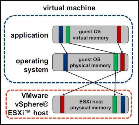
Hardware-Assisted Memory Virtualization
Some CPUs, such as AMD SVM-V and the Intel Xeon 5500 series, provide hardware support for memory virtualization by using two layers of page tables.
Note:
In this topic, "Memory" can refer to physical RAM or Persistent Memory.
The first layer of page tables stores guest virtual-to-physical translations, while the second layer of page tables stores guest physical-to-machine translation. The TLB (translation look-aside buffer) is a cache of translations maintained by the processor's memory management unit (MMU) hardware. A TLB miss is a miss in this cache and the hardware needs to go to memory (possibly many times) to find the required translation. For a TLB miss to a certain guest virtual address, the hardware looks at both page tables to translate guest virtual address to machine address. The first layer of page tables is maintained by the guest operating system. The VMM only maintains the second layer of page tables.
Performance Considerations
When you use hardware assistance, you eliminate the overhead for software memory virtualization. In particular, hardware assistance eliminates the overhead required to keep shadow page tables in synchronization with guest page tables. However, the TLB miss latency when using hardware assistance is significantly higher. By default the hypervisor uses large pages in hardware assisted modes to reduce the cost of TLB misses. As a result, whether or not a workload benefits by using hardware assistance primarily depends on the overhead the memory virtualization causes when using software memory virtualization. If a workload involves a small amount of page table activity (such as process creation, mapping the memory, or context switches), software virtualization does not cause significant overhead. Conversely, workloads with a large amount of page table activity are likely to benefit from hardware assistance.
By default the hypervisor uses large pages in hardware assisted modes to reduce the cost of TLB misses. The best performance is achieved by using large pages in both guest virtual to guest physical and guest physical to machine address translations.
Virtual machine memory overcommit
The total configured memory sizes of all VMs might exceed the amount of available physical memory on the host.
Memory is overcommitted when the working memory size of all VMs exceeds that of the ESXi host’s physical memory size
When memory is overcommitted: •
- VMs do not always use their full allocated memory.
- To improve memory usage, an ESXi host transfers memory from idle VMs to VMs that need more memory.
- Overcommitted memory is stored in the .vswp file.
- Memory overhead is stored in the vmx-*.vswp file.
Memory overcommit techniques
An ESXi host uses memory overcommit techniques to allow the overcommitment of memory while possibly avoiding the need to page memory out to disk.
Methods Used by the ESXi Host       Explanation
Transparent page sharing        This method economizes the use of physical memory pages.
                                In this method, pages with identical contents are stored only once.
Ballooning                      This method uses the VMware Tools balloon driver to deallocate memory from one VM to another.
                                The ballooning mechanism becomes active when memory is scarce, forcing VMs to use their own paging areas.
Memory compression              This method tries to reclaim some memory performance when memory contention is high.
Host-level SSD swapping         Use of a solid-state drive on the ESXi host for a host cache swap file might increase performance.
VM memory paging to disk        Using VMkernel swap space is the last resort because of poor performance.
To use ballooning, the guest operating system must be configured with sufficient swap space.
Configuring Multicore VM
The following url provides quite detail explanation about CPU
https://www.nakivo.com/blog/the-number-of-cores-per-cpu-in-a-virtual-machine/
The number of logical CPUs means the number of physical processor cores or two times that number if hyperthreading is enabled.
Setting the number of cores per CPU in a virtual machine (1010184) https://kb.vmware.com/s/article/1010184
Every 2 milliseconds to 40 milliseconds, the VMkernel seeks to migrate vCPUs from one logical processor to another to keep the load balanced. The VMkernel does its best to schedule VMs with multiple vCPUs on two different cores rather than on two logical processors on the same core.
Resource Control
Reservations, Limits and Shares
Configure resource allocation settings to a VM to control the amount of resources granted:
- A reservation specifies the guaranteed minimum allocation for a VM.
- A limit specifies an upper bound for CPU or memory that can be allocated to a VM.
- A share is a value that specifies the relative priority or importance of a VM's access to a given resource
Memory reservation
Note: Adding a vSphere DirectPath I/O device to a VM sets memory reservation to the memory size of the VM
CPU reservation
CPU that is reserved for a VM is guaranteed to be immediately scheduled on physical cores. The VM is never placed in a CPU ready state.
Resource Allocation Shares
Shares define the relative importance of a VM:
- If a VM has twice as many shares of a resource as another VM, the VM is entitled to consume twice as much of that resource when these two VMs compete for resources.
- Share values apply only if an ESXi host experiences contention for a resource.
You can set shares to high, normal, or low. You can also select the custom setting to assign a specific number of shares to each VM.
Setting CPU Share Values        Memory Share Values
High    2,000 shares per vCPU   20 shares per MB of configured VM memory
Normal  1,000 shares per vCPU   10 shares per MB of configured VM memory
Low     500 shares per vCPU     5 shares per MB of configured VM memory

High, normal, and low settings represent share values with a 4:2:1 ratio.
View VM Resource Allocation Settings
1. In vSphere client, select data center or cluster
2. Select Monitor on the right pane
3. Navigate to Resource Allocation, choose
    a. CPU
    b. Memory
    c. Storage
It will display all VMs resource allocation settings
Resource-Monitoring Tool
There are many resource monitoring and performance monitoring tools are available for use:
# Inside the guest OS
1. Windows
    a. Perfmon
    b. Task Manager
    c. sysinternals tools/utilities
2. Linux
    a. top      command
# Outside the guest OS
    a. vCenter Server performance charts
    b. vRealize Operations
    c. vSphere/ESXi system logs
    d. resxtop and esxtop
The esxtop utility is the primary real-time performance monitoring tool for vSphere:
1. Can be run from the host’s local vSphere ESXi Shell as esxtop
2. Can be run remotely from vSphere CLI as resxtop
3. Works like the top performance utility in Linux operating systems
vSphere inventory objects with performance charts
The vSphere statistics subsystem collects data on the resource usage of inventory objects, which include:
1. Clusters
2. Hosts
3. Datastores
4. Networks
5. Virtual machines
Advanced Performance Charts
Advanced charts support data counters that are not supported in other performance charts.
In the vSphere Client, you can customize the appearance of advanced performance charts.
Advanced charts have the following features:
- More information than overview charts: Point to a data point in a chart to display details about that specific data point.
- Customizable charts: Change chart settings. Save custom settings to create your own charts.
- Save data to an image file or a spreadsheet.
To customize advanced performance charts:
1. select Advanced under Performance.
2. Click the Chart Options link in the Advanced Performance pan
Chart options - real-time and historical
# vCenter Server stores statistics
Time Interval       Data Frequency  Number of Samples
Real-time (past hour) 20 seconds    180
Past day            5 minutes       288
Past week           30 minutes      336
Past month          2 hours         360
Past year           1 day           365
On ESXi hosts, the statistics are kept for 30 minutes, after which 90 data points are collected. The data points are aggregated, processed, and returned to vCenter Server. vCenter Server then archives the data in the database as a data point for the day collection interval.
Performance statistic type explanation
The statistics type is the unit of measurement that is used during the statistics interval.
The statistics type is one of the following:
- Rate: Value over the current statistics interval
- Delta: Change from the previous statistics interval
- Absolute: Absolute value (independent of the statistics interval)
For example, CPU usage is a rate, CPU ready time is a delta, and memory active is an absolute value.
For real-time data, the value is the current minimum or current maximum. For historical data, the value is the average minimum or average maximum.
Monitoring Resource Use
Monitor CPU utilization
https://geek-university.com/vmware-esxi/monitor-cpu-utilization/
You can use the CPU performance charts to monitor CPU usage for hosts, clusters, resource pools, virtual machines, and vApps. . A good indicator of a CPU-constrained virtual machine is the CPU ready time value. This value shows how long a VM is waiting to be scheduled on a logical processor.
# How to display CPU ready time using vSphere client
1. Select the ESXi host from the inventory and select Monitor > Performance > Advanced.
2. In the Advanced window, click the Chart Options link
3. The Chart Options wizard opens. Select CPU as the chart metric.
4. Set the timespan as Real-time and Line Graph as the chart type.
5. Select only your ESXi host under Select object for this chart.
6. Under Select counters for this chart, select Ready
Monitor memory utilization
Any evidence of ballooning or swapping is a sign that your host might be memory-constrained.
Monitor disk access
Disk-intensive applications can saturate the storage or the path.
 # When a VM is constrained by disk access
 1. Measure the throughput and latency between the VM and storage.
 2. Use the advanced performance charts to monitor throughput and latency
    a. Read rate and write rate
    b. Read latency and write latency
Monitoring Disk Latency
To determine disk performance problems, monitor two disk latency data counters
1. Kernel command latency
    a. This counter is the average time that is spent in the VMkernel per SCSI command.
    b. High numbers (greater than 2 milliseconds or 3 milliseconds) represent either an overworked array or an overworked host.
2. Physical device command latency
    a. This counter is the average time that the physical device takes to complete a SCSI command.
    b. High numbers represent a slow or overworked array, for example
        i. For spinning disks (HDDs), greater than 15 milliseconds or 20 milliseconds
        ii. For SSDs, greater than 3 milliseconds or 4 milliseconds

To determine whether the vSphere environment is experiencing disk problems, monitor the disk latency data counters.
Use the advanced performance charts to view these statistics.
Monitor network
When a VM is constrained by the network
- Verify that VMware Tools is installed and that VMXNET3 is the virtual network adapter
- Measure the effective bandwidth between the VM and its peer system
- Check for dropped receive packets (droppedRx) and dropped transmit packets (droppedTx )
Using Alarms
An alarm is a notification that is sent in response to an event or condition that occurs with an object in the inventory.
Preconfigured vSphere alarms https://docs.vmware.com/en/VMware-vSphere/7.0/com.vmware.vsphere.monitoring.doc/GUID-82933270-1D72-4CF3-A1AF-E5A1343F62DE.html
How to configure and manage vSphere 7 alarms
https://4sysops.com/archives/how-to-configure-and-manage-vsphere-7-alarms/
vCenter Server provides a list of default alarms, which monitor the operations of vSphere inventory objects. You must only set up actions for these alarms.
Some alarms are stateless. vCenter Server does not keep data on stateless alarms, does not compute, or display their status. Stateless alarms cannot be acknowledged or reset. Stateless alarms are indicated by an asterisk next to their name.
Creating vCenter Alarms based on Task Events
# How to make a copy of an alarm
1. Select an inventory object in vSphere client
2. Select Configure, then expand security, and select Alarm Definitions
3. Select an existing alarm, then click ADD
Configure vCenter Server Notifications
If you use email or SNMP traps as the notification method, you must configure vCenter Server to support these notification methods.
1. Select vCentr object in vSphere client
2. Select Configure, then expand Settings -> General
3. Click Edit
4. Enter value in
    a. Mail
    b. SNMP receivers
vSphere Clusters
High Availability and Load Balancing with VMware Clusters
https://www.parallels.com/blogs/ras/vmware-clusters/
A cluster is used in vSphere to share physical resources between a group of ESXi hosts. vCenter Server manages cluster resources as a single pool of resources.
Note:
1. A cluster supports up to 96 ESXi hosts.
2. vSAN configured cluster support up to 64 hosts per cluster.
When you create a cluster, you can activate one or more cluster features:
1. vSphere DRS
2. vSphere HA
3. vSAN

You could enable "Manage all hosts in the cluster with a single image.
Note:
    With vSphere Lifecycle Manager, you can update all hosts in the cluster collectively, using a specified ESXi image.
Configuring the cluster using Quickstart
After creating the cluster, you can use the Cluster Quickstart workflow to configure the cluster. With Cluster Quickstart, you follow a step-by-step configuration wizard that makes it easy to expand the cluster as needed. It covers every aspect of the initial configuration, such as host, network, and vSphere settings.
vSphere cluster services (vCLs)
VMware introduced vSphere Cluster Services (vCLS) in vSphere 7.0 Update 1. These vCLS mini-VMs, also called agent VMs, must be run on the cluster. The vCLS VM will appear after upgrading to vSphere 7.0 Update 1, the VM appear on your VMware vSphere cluster called “vCLS”, maybe multiple VMs appeared named “vCLS (1)”, “vCLS (2)”, “vCLS (3)”.
The vCLS VMs are created when hosts are added to a vSphere Cluster. Up to 3 vCLS VMs are required to run in each vSphere Cluster.
In vSphere 7.0 U2, vSphere Cluster Services (vCLS) is enabled by default and runs in all vSphere clusters. vCLS ensures that if vCenter Server becomes unavailable, cluster services remain available to maintain the resources and health of the workloads that run in the clusters. vCenter Server is still required in 7.0 U2 to run DRS and HA.
vCLS is enabled when you upgrade to vSphere 7.0 U2 or when you have a new vSphere 7.0 U2 deployment. vCLS is upgraded as part of vCenter Server upgrade.
vCLS uses agent virtual machines to maintain cluster services health. The vCLS agent virtual machines (vCLS VMs) are created when you add hosts to clusters. Up to three vCLS VMs are required to run in each vSphere cluster, distributed within a cluster. vCLS is also enabled on clusters which contain only one or two hosts. In these clusters the number of vCLS VMs is one and two, respectively.
# Number of vCLS Agent VMs in Clusters
Number of Hosts in a Cluster    Number of vCLS Agent VMs
-------------------------------------------------------------
        1                       1
        2                       2
        3 or more               3
vCLS VMs run in every cluster even if cluster services like vSphere DRS or vSphere HA are not enabled on the cluster. The lifecycle operations of vCLS VMs are managed by vCenter services like ESX Agent Manager and Workload Control Plane. In vSphere 7.0 U2, vCLS VMs do not support NiC cards.
vSphere DRS
https://www.vmware.com/au/products/vsphere/drs-dpm.html
https://4sysops.com/archives/vmware-vsphere-7-drs-scoring-and-configuration/
https://houseofbrick.com/whats-new-with-distributed-resource-scheduling-drs-in-vsphere-7/
The purpose of DRS is to balance CPU and memory across clusters. Due to the variable nature of database workloads, it is generally not desirable to allow vSphere DRS to relocate production databases automatically.
vSphere 7 DRS logic has changed most significantly in regard to the balancing approach. Prior versions of DRS balanced at the vSphere cluster level. It would review ESXi hosts for high memory and CPU usage and attempt to balance the cluster more equally. With vSphere 7, DRS evaluates virtual machine performance instead of the cluster, and also has more granular checks, looking at metrics like CPU Ready Time and memory ballooning. Now, if DRS can provide better performance to a VM on another ESXi host, it will move it or make a recommendation for it to be moved. DRS now uses a score to determine the performance efficiency of the virtual machine.
VM DRS score
https://blogs.vmware.com/vsphere/2020/05/vsphere-7-a-closer-look-at-the-vm-drs-score.html
The fundamental concept of the new DRS logic is that VMs have an ideal throughput and an actual throughput for each resource (CPU, memory, and network). When there is no contention, the ideal throughput of that VM is equal to the actual throughput. We talk about resource contention if multiple VMs are in conflict over access to a shared compute or network resource. In the situation when there is contention for a resource, there is a cost for that resource that hurts the actual VM throughput.
Based on these statements, here are some equations
Goodness (actual throughput) = Demand (ideal throughput) – Cost (loss of throughput)
Efficiency = Goodness (actual throughput) / Demand (ideal throughput)
Total efficiency = EfficiencyCPU * EfficiencyMemory * EfficiencyNetwork
Total efficiency on host = VM DRS score

1. Values closer to 0% indicate severe resource contention.
2. Values closer to 100% indicate mild to no resource contention.
We can view VM DRS scores in performance charts. The advanced performance chart for a cluster object provides the DRS Score counter.
vSphere DRS is used in the following situations:
- Initial placement of a VM when it is powered on
- Load balancing
- Migrating VMs when an ESXi host is placed in maintenance mode
DRS Comparison
Settings        DRS before vSphere 7    vSphere 7 DRS
-------------------------------------------------------------
DRS Check Run   Every 5 minutes         Every 1 minutes
DRS logic       cluster based           VM based
DRS checks      CPU and memory usage    more granular check for CPU and memory
DRS recommedation   Capacity based      Score base (capacity and performance)
VM DRS Scores
To view the VM DRS scores in the cluster
1. Select the cluster in vSphere client
2. Click Monitor tab
3. Navigate to vSphere DRS -> VM DRS Score
Note: VM DRS scoe only hows the powered on VM.
It shows the following values
- DRS Score
- Active CPU
- Used CPU
- CPU Readiness
- Granted Memory
- Swapped Memory
- Ballooned Memory
vSphere DRS settings
There are three automation levels: Manual, Partially Automated, Fully Automated
Migration Threshold: Conservative (less Frequent vMotions) to Aggresive (More Frequent vMotion)
Predicted DRS
The vSphere DRS data collector retrieves the following data
- Resource usage statistics from ESXi hosts
- Predicted usage statistics from the vRealize Operations Manager server
Affinity rules
https://4sysops.com/archives/configuration-of-vsphere-7-drs-affinity-and-anti-affinity-rules/
A VM-Host affinity rule specifies whether or not the members of a selected virtual machine DRS group can run on the members of a specific host DRS group.
Unlike a VM-VM affinity rule, which specifies affinity (or anti-affinity) between individual virtual machines, a VM-Host affinity rule specifies an affinity relationship between a group of virtual machines and a group of hosts. There are 'required' rules (designated by "must") and 'preferential' rules (designated by "should".)
A VM-Host affinity rule includes the following components
- One virtual machine DRS group.
- One host DRS group.
- A designation of whether the rule is a requirement ("must") or a preference ("should") and whether it is affinity ("run on") or anti-affinity ("not run on").
Because VM-Host affinity rules are cluster-based, the virtual machines and hosts that are included in a rule must all reside in the same cluster. If a virtual machine is removed from the cluster, it loses its DRS group affiliation, even if it is later returned to the cluster.
vSphere DRS is used in the following situations:
- Initial placement of a VM when it is powered on
- Load balancing
- Migrating VMs when an ESXi host is placed in maintenance mode
DRS VM/Host Rules
vSphere VM/Host affinity rule type
- Keep Virtual Machine Together
- Separate Virtual Machines
- Virtual Machines to Hosts
- Virtual Machines to Virtual Machines
DRS VM/Host Groups
VM/Host groups defines virtual machine group and host group. The DRS rule then can be applied to these VM or host groups.
A VM can belong to multiple VM groups
A host can belong to multiple host groups
Affinity Must Rule
It is recommended to set host affinity “Must” rules for VMs that need to stay on certain hosts for licensing purposes. Configuring host affinity rules to be set that define where VMs can or cannot (anti-affinity) run.
# Prerequisites
Create the virtual machine and host DRS groups to which the VM-Host affinity rule applies.

# Procedure
1. Browse to the cluster in the vSphere Client.
2. Click the Configure tab.
3. Under Configuration, click VM/Host Rules.
4. Click Add.
5. In the Create VM/Host Rule dialog box, type a name for the rule.
6. From the Type drop down menu, select Virtual Machines to Hosts.
7. Select the virtual machine DRS group and the host DRS group to which the rule applies.
8. Select a specification for the rule.
    a. Must run on hosts in group. Virtual machines in VM Group 1 must run on hosts in Host Group A.
    b. Should run on hosts in group. Virtual machines in VM Group 1 should, but are not required, to run on hosts in Host Group A.
    c. Must not run on hosts in group. Virtual machines in VM Group 1 must never run on host in Host Group A.
    d. Should not run on hosts in group. Virtual machines in VM Group 1 should not, but might, run on hosts in Host Group A.
9. Click OK.
VM-Host Affinity Rules
A VM-Host affinity rule
- Defines an affinity (or anti-affinity) relationship between a VM group and a host group
- Is either a required rule or a preferential rule
Rule options
- Must run on hosts in group
- Should run on hosts in group
- Must not run on hosts in group
- Should not run on hosts in grou
# VM affinity rule or affinity rules for VMs
It defines affinity or anti-affinity between individual VMs.

# VM-Host affinity rule
It defines an affinity or anti-affinity relationship between a groupo of VMs and a group of hosts.

Because VM-Host affinity rules are cluster-based, the VMs and hosts that are included in a rule must all reside in the same cluster.
If a VM is removed from the cluster, the VM loses its membership from all VM groups, even if it is later returned to the cluster.
VM-Host affinity preferential rules
A preferential rule is softly enforced and can be violated if necessary.
ESXi host maintenance mode and Standby mode
Maintenance mode
- Removes a host's resources from a cluster, making those resources unavailable for use •
- It is used to service a host in a cluster, such as firmware upgrade or patching
Standby mode
When a host is placed in standby mode, it is powered off.
You can place a host in standby mode manually. However, the next time that vSphere DRS runs, it might undo your change or recommend that you undo the changes. If you want a host to remain powered off, place it in maintenance mode and turn it off.
# How to remove a host from vSphere DRS cluster
1. Place the host in maintenance mode.
2. Drag the host to a different inventory location, for example, the data center or another cluster.
vSphere DRS and Dynamic DirectPath I/O or Assignable Hardware
https://blogs.vmware.com/vsphere/2020/03/vsphere-7-assignable-hardware.html
The above URL provides detail information about dynamic DirectPath I/O or Assignable hardware.
Assignable Hardware in vSphere 7 provides a flexible mechanism to assign hardware accelerators to workloads. This mechanism identifies the hardware accelerator by attributes of the device rather than by its hardware address. This allows for a level of abstraction of the PCIe device. Assignable Hardware implements compatibility checks to verify that ESXi hosts have assignable devices available to meet the needs of the virtual machine.
It integrates with Distributed Resource Scheduler (DRS) for initial placement of workloads that are configured with a hardware accelerator. This also means that Assignable Hardware brings back the vSphere HA capabilities to recover workloads (that are hardware accelerator enabled) if assignable devices are available in the cluster. This greatly improves workload availability.

Note:
1. Select the required VM, and click Edit
2. Add New PCI device or edit an existing PCI Device
3. Select one of the following type
    a. Directpath IO    # traditional host-bounded assignment
    b. DynamicPath IO   # vsphere 7 new feature
    c. NVIDIA GRID vGPU
vSphere VMDirectPath I/O and Dynamic DirectPath I/O: Requirements for Platforms and Devices (2142307)
https://kb.vmware.com/s/article/2142307
How to configure DirectPath I/O and Dynamic DirectPath I/O passthrough modes on VMware ESXi 7.0.
https://docs.mellanox.com/m/view-rendered-page.action?abstractPageId=25146879
Using GPUs with Virtual Machines on vSphere
vSphere HA
https://www.vmware.com/au/products/vsphere/high-availability.html
https://4sysops.com/archives/configure-vmware-vsphere-7-high-availability-advanced-options/
vSphere HA provides high availability for virtual machines by pooling the virtual machines and the hosts they reside on into a cluster. Hosts in the cluster are monitored and in the event of a failure, the virtual machines on a failed host are restarted on alternate hosts.
When you create a vSphere HA cluster, a single host is automatically elected as the primary host. The primary host communicates with vCenter Server and monitors the state of all protected virtual machines and of the secondary hosts. Different types of host failures are possible, and the primary host must detect and appropriately deal with the failure. The primary host must distinguish between a failed host and one that is in a network partition or that has become network isolated. The primary host uses network and datastore heartbeating to determine the type of failure.
vSphere HA - Datastore accessibility failures
If VM Component Protection (VMCP) is configured, vSphere HA can detect datastore accessibility failures and provide automated recovery for affected VMs.
We can determine the response that vSphere HA makes to such a failure, ranging from the creation of event alarms to VM restarts on other hosts:
- All paths down (APD)
a. Recoverable
b. Represents a transient or unknown accessibility loss.
c. Response can be either
    i. Issue events
    ii. Power off and restart VMs - Conservative restart policy
    iii. Power off and restart VMs - Aggressive restart policy.
- Permanent device loss (PDL)
a. Unrecoverable loss of accessibility.
b. Occurs when a storage device reports that the datastore is no longer accessible by the host.
c. Response can be either Issue events or Power off and restart VMs.
vSphere HA Network
A heartbeat network is implemented in the following ways
- By using a VMkernel port that is marked for management
- By using a VMkernel port that is marked for vSAN traffic when vSAN is in use
You can use NIC teaming to create a redundant heartbeat network on ESXi hosts.
You can create redundancy by configuring more heartbeat networks. On each ESXi host, create a second VMkernel port on a separate virtual switch with its own physical adapter.
In most implementations, NIC teaming provides sufficient heartbeat redundancy.
Communication between vCenter Server and ESXi hosts
The main service running on the vCenter Server is known as vpxd or VMware Virtual Server service. When an ESXi host is added to the vCenter Server, there is an agent service called vpxa, which is installed and started on the ESXi host. Vpxa acts as an intermediary service between the vpxd service running on the vCenter Server and hostd service running on the ESXi host. The hostd service running on the ESXi host is mainly responsible for managing most of the operations on the host.
        vCenter Server (vpxd)
         |              |
         |              |
TCP/UDP  |              | TCP 443, 9443
  902    |              |
         |          vSphere client
         |
      ESXi Host
        (vpxa)

# Restart the ESXi host daemon and vCenter agent services
/etc/init.d/hostd restart
/etc/init.d/vpxa  restart
When the primary host cannot communicate with a secondary host over the management network, the primary host uses datastore heartbeating to determine the cause
- Secondary host failure
- Network partition
- Network isolation
Using datastore heartbeating, the primary host determines whether a host has failed or a network isolation has occurred. If datastore heartbeating from the host stops, the host is considered failed. In this case, the failed host’s VMs are started on another host in the vSphere HA cluster.
Isolated hosts
A host is declared isolated when the following conditions occur
- The host is not receiving network heartbeats.
- The host cannot ping its isolation addresses.
default isolation address: default gateway
Datastore heartbeats are used by vSphere HA only when a host becomes isolated or partitioned.
VM storage failure
Storage connectivity problems might arise because of
- Network or switch failure
- Array misconfiguration
- Power outage
VM Component Protection
VM Component Protection protects against storage failures on a VM. If VMCP is configured, vSphere HA can detect datastore accessibility failures and provide automated recovery for affected VMs.
VMCP is not supported with vSAN.
vSphere HA Design Considerations
When designing vSphere HA cluster, consider these guidelines:
- Implement redundant heartbeat networks and redundant isolation addresses Redundancy minimizes host isolation events.
- Physically separate VM networks from the heartbeat networks.
- Implement datastores so that they are separated from the management network by using one or both of the following approaches. a. Use Fibre Channel over fiber optic for your datastores. b. If you use IP storage, physically separate your IP storage network from the management network.
If a datastore is based on Fibre Channel, a network failure does not disrupt datastore access. When using datastores based on IP storage (for example, NFS, iSCSI, or Fibre Channel over Ethernet), you must physically separate the IP storage network and the management network (the heartbeat network). If physical separation is not possible, then logically separate the networks.
Configuring vSphere HA Settings
When we create or configure a vSphere HA cluster, we must configure settings that determine how the feature works.
# Configure vSphere HA Settings in the vSphere client
1. Select the cluster -> Configure
2. Expand Services -> vSphere Availability
3. Under Failures and Responses
    a. Host Failure Response, select option, such as Restart VM
    b. Response for Host Isolation, select option, such as Disabled
    c. Datastore with PDL, select option, such as Power off and restart VMs
    d. Datastore with APD, select option, such as Power off and restart VM - conservative restart policy
    e. VM Monitoring, select option Disabled
4. Admission control
    Activate or deactivate admission control for the vSphere HA cluster and select a policy for how it is enforced.
5. Heartbeat datastores
    Specify preferences for the datastores that vSphere HA uses for datastore heart-eating.
6. Advanced options
    Customize vSphere HA behavior by setting advanced option
vSphere HA Settings - Admission Control
vCenter Server uses admission control to ensure both that sufficient resources are available in a cluster to provide failover protection and that VM resource reservations are respected.
The admission control settings include
- Disabled: (Not recommended) - This option deactivates admission control, allowing the VMs violating availability constraints to power on.
- Slot Policy - A slot is a logical representation of memory and CPU resources. With the slot policy option, vSphere HA calculates the slot size, determines how many slots each host in the cluster can hold, and therefore determines the current failover capacity of the cluster.
- Cluster resource Percentage - (Default) This value specifies a percentage of the cluster’s CPU and Memory resources to be reserved as spare capacity to support failovers.
- Dedicated failover hosts - This option selects hosts to use for failover actions. If a default failover host does not have enough resources, failovers can still occur to other hosts in the cluster.
The Admission Control page appears only if you enabled vSphere HA.
# Procedure
1. In the vSphere Client, browse to the vSphere HA cluster.
2. Click the Configure tab.
3. Select vSphere Availability and click Edit.
4. Click Admission Control to display the configuration options.
5. Select a number for the Host failures cluster tolerates.
    This is the maximum number of host failures that the cluster can recover from or guarantees failover for.
6. Select an option for Define host failover capacity by.
Option                          Description
----------------------------------------------------------------
Cluster resource percentage     Specify a percentage of the cluster’s CPU and memory resources to reserve as spare capacity to support failovers.
Slot Policy (powered-on VMs)    Select a slot size policy that covers all powered on VMs or is a fixed size.
                                You can also calculate how many VMs require multiple slots.
Dedicated failover hosts        Select hosts to use for failover actions.
                                Failovers can still occur on other hosts in the cluster if a default failover host does not have enough resources.
Disabled                        Select this option to disable admission control and
                                allow virtual machine power on that violate availability constraints.

7. Set the percentage for the Performance degradation VMs tolerate.
    This setting determines what percentage of performance degradation the VMs in the cluster are allowed to tolerate during a failure.
8. Click OK.
### Admission control using slots
A slot is calculated by combining the largest memory reservation and the largest CPU reservation of any running VM in the cluster.
vSphere HA Orchestrated Restart
Orchestrated restart in vSphere HA enables five tiers for restarting VM and VM-VM dependencies.
Network configuration and maintenance
Deactivate host monitoring before modifying virtual networking components that involve the VMkernel ports configured for management or vSAN traffic. This will prevent unwanted attempts to fail over VMs.
1. In vSphere client, select the cluster
2. Right click and choose Edit
3. In Failure and response tab, do not select "Enable Host Monitoring"
Recommendated Practices
- When changing the management or vSAN networks of the hosts in the vSphere HA-configured cluster, suspend host monitoring and place the host in maintenance mode.
- Deactivating host monitoring is required only when modifying virtual networking components and properties that involve the VMkernel ports configured for the Management or vSAN traffic, which are used by the vSphere HA networking heartbeat service.
- After you change the networking configuration on ESXi hosts, for example, adding port groups, removing virtual switches, or suspending host monitoring, you must reconfigure vSphere HA on all hosts in the cluster. This reconfiguration causes the network information to be reinspected. Then, you must reactivate host monitoring.
vSphere HA might not be able to fail over VMs for the following reasons:
- vSphere HA admission control is deactivated, and resources are insufficient in the remaining hosts to power on all the failed VMs.
- Sufficient aggregated resources exist, but they are fragmented across hosts. In such cases, vSphere HA uses vSphere DRS to try to adjust the cluster by migrating VMs to defragment the resources
vSphere Proactive HA
You can configure how Proactive HA responds when a provider has notified its health degradation to vCenter, indicating a partial failure of that host.
This page is editable only if you have enabled vSphere DRS.
Deployment Note:
vSphere Distributed Resource Scheduler (DRS) is the prerequisite for Proactive HA
# Procedure
1. In the vSphere Client, browse to the Proactive HA cluster.
2. Click the Configure tab.
3. Select vSphere Availability and click Edit.
4. Select Turn on Proactive HA.
5. Click Proactive HA Failures and Responses.
6. Select from the following configuration options
    a. Automation Level
        i. Manual
        ii. Automated
    b. Remediation
        Determine what happens to partially degraded hosts.
        i. Quarantine mode for all failures.
            Balances performance and availability, by avoiding the usage of partially degraded hosts
            provided that virtual machine performance is unaffected.
        ii. Quarantine mode for moderate and Maintenance mode for severe failure (Mixed).
            Balances performance and availability, by avoiding the usage of moderately degraded hosts
            provided that virtual machine performance is unaffected. Ensures that virtual machines do not run on severely failed hosts.
        iii. Maintenance mode for all failures.
            Ensures that virtual machines do not run on partially failed hosts.
    To enable Proactive HA providers for this cluster, select the check boxes.
7. click OK
vSphere Fault Tolerance
https://4sysops.com/archives/vmware-vsphere-6-7-fault-tolerance-the-ultimate-vm-protection/
vSphere Fault Tolerance (FT) provides continuous availability for most mission critical virtual machines by creating and maintaining another VM that is identical and continuously available to replace it in the event of a failover situation.
The protected virtual machine is called the Primary VM. The duplicate virtual machine, the Secondary VM, is created and runs on another host. The primary VM is continuously replicated to the secondary VM.
A transparent failover occurs if the host running the Primary VM fails, in which case the Secondary VM is immediately activated to replace the Primary VM. A new Secondary VM is started and Fault Tolerance redundancy is reestablished automatically. If the host running the Secondary VM fails, it is also immediately replaced.
Fault Tolerance avoids "split-brain" situations, which can lead to two active copies of a virtual machine after recovery from a failure. Atomic file locking on shared storage is used to coordinate failover so that only one side continues running as the Primary VM and a new Secondary VM is respawned automatically.
vSphere Fault Tolerance can accommodate symmetric multiprocessor (SMP) virtual machines with up to four vCPUs.
vSphere fault tolerance checkpoint
Changes on the primary VM are not processed on the secondary VM. The memory is updated on the secondary VM. The vSphere Fault Tolerance checkpoint interval is dynamic. It adapts to maximize the workload performance.
The primary VM is copied (checkpointed) periodically, and the copies are sent to a secondary host. If the primary host fails, the VM continues on the secondary host at the point of its last network send. The goal is to take checkpoints of VMs at least every 10 milliseconds.
vSphere Fault Tolerance Shared Files
vSphere Fault Tolerance has shared files.
1. shared.vmft file
    It ensures that the primary VM always retains the same UUID.
    This file contains the primary and secondary instance UUIDs and the primary and secondary vmx paths.
2. The .ft-generation file
    It is for the split-brain conditiion.
    It ensures that only one VM instance is designated as the primary VM.
Limits
In a cluster configured to use Fault Tolerance, two limits are enforced independently.
- das.maxftvmsperhost
The maximum number of fault tolerant VMs allowed on a host in the cluster. The default value is 4. There is no FT VMs per host maximum, you can use larger numbers if the workload performs well in FT VMs. You can disable checking by setting the value to 0. 2. das.maxftvcpusperhost The maximum number of vCPUs aggregated across all fault tolerant VMs on a host. The default value is 8. There is no FT vCPU per host maximum, you can use larger numbers if the workload performs well. You can disable checking by setting the value to 0.
Licensing
The number of vCPUs supported by a single fault tolerant VM is limited by the level of licensing that you have purchased for vSphere. Fault Tolerance is supported as follows:
1. vSphere Standard and Enterprise. Allows up to 2 vCPUs
2. vSphere Enterprise Plus. Allows up to 8 vCPUs
vSphere Fault Tolerance:
1. Supports VMs configured with up to 8 vCPUs and 128 GB memory
2. Supports up to four fault-tolerant VMs per host with no more than eight vCPUs between them
3. Can be used with vSphere DRS only when Enhanced vMotion Compatibility is configured
    We can use vSphere Fault Tolerance with vSphere DRS only when the Enhanced vMotion Compatibility feature is configured.
4. Supports interoperability with vSAN

# Incompatible with FT
    Fault Tolerance is not supported with a 2TB+ VMDK.
When vSphere Fault Tolerance is used for VMs in a cluster that has EVC mode deactivated, the fault-tolerant VMs are given the Disabled vSphere DRS automation level. In such a cluster, each primary VM is powered on only on its registered host, and its secondary VM is automatically placed.
vSphere Fault Tolerance with vSphere HA and vSphere DRS
vSphere HA and vSphere DRS are vSphere Fault Tolerance aware:
1. vSphere HA
    a. Is required for vSphere Fault Tolerance
    b. Restarts failed VMs
2. vSphere DRS
    a. Selects which hosts run the primary and secondary VM, when a VM is powered on
    b. Does not automatically migrate fault-tolerant VMs
How to turn on virtual machine vSphere FT
1. Select the required VM
2. Right click and select Fault Tolerance
3. Select required options
    a. Turn On Fault Tolerance
    b. Turn Off Fault Tolerance
    c. Resume Fault Tolerance
    d. Suspend Fault Tolerance
    e. Migrate Secondary
    f. Test Failover
    g. Testing restart of secondary VM
When vSphere Fault Tolerance is turned on, vCenter Server resets the VM’s memory limit to the default (unlimited memory) and sets the memory reservation to the memory size of the VM. While vSphere Fault Tolerance is turned on, you cannot change the memory reservation, size, limit, number of virtual CPUs, or shares. You also cannot add or remove disks for the VM. When vSphere Fault Tolerance is turned off, any parameters that were changed are not reverted to their original values.
vSphere Cluster Service
vSphere Cluster Services (vCLS) in vSphere 7.0 Update 1 (80472)
https://kb.vmware.com/s/article/80472
vSphere Cluster Services (vCLS) is a new feature in vSphere 7.0 Update 1. This feature ensures cluster services such as vSphere DRS and vSphere HA are all available to maintain the resources and health of the workloads running in the clusters independent of the vCenter Server instance availability.
In vSphere 7.0 Update 1, VMware has released a platform/framework to facilitate them to run independently of the vCenter Server instance availability. vCLS ensures that if vCenter Server becomes unavailable, cluster services remain available to maintain the resources and health of the workloads that run in the clusters. vCenter Server is still required for running cluster services such as vSphere DRS, vSphere HA etc.
vSphere cluster service VMs
The vSphere Cluster Service deploys vSphere Cluster Service virtual machines (vCLS VMs) to each vSphere cluster that is managed by vCenter Server 7.0 Update 1. vSphere Cluster Service VMs are deployed to a cluster at creation and after hosts are added to the cluster.
Note:
1. vSphere DRS depends on the health of the vSphere Cluster Services starting with vSphere 7.0 Update 1.
    vSphere Distributed Resource Scheduler (vSphere DRS) cannot function if vSphere Cluster Service VMs are not present in the vSphere cluster.
2. vSphere clusters do not require ESXi 7.0 Update 1.
3. vSphere Cluster Service VMs can be deployed to clusters with ESXi 6.5, ESXi 6.7, or ESXi 7.0.
The vSphere Cluster Service introduces vSphere Cluster Service Manager (wcpsvc) and vSphere Cluster Service Resource Manager (vpxd).
Each vSphere Cluster Service component performs a unique function:
1. vSphere Cluster Service Manager:
    a. New module running in the wcpsvc service
    b. Manages and monitors a vSphere ESX Agent Manager agency for each set of cluster VMs
    c. Persists the EAM agency information in the vCenter Server database
    d. Customizes each cluster VM during deployment
    e. Performs password rotation for vSphere cluster service VMs
    f. Operates a desired state model
2. ESX Agent Manager (EAM):
    a. Deploys vSphere Cluster Service VMs to the ESXi hosts in the vSphere cluster
    b. Receives VM placement information from vSphere Cluster Service Resource Manager
3. vSphere Cluster Service Resource Manager:
    a. New module running in the vmware-vpxd service
    b. Manages vSphere Cluster Service VM initial placement and failover placement
4. vSphere Cluster Service OVF:
    a. Virtual machine OVF template for vSphere Cluster Service VMs
    b. Stored at /storage/lifecycle/vmware-hdcs/ in vCenter Server.
    c. vCenter Server patches and updates replace the OVF template with updated versions, if needed.
vSphere cluster service VM do not have an assigned network interface card (NIC) or IP address.
vSphere Cluster Service VMs are visible when connected directly to an ESXi host using VMware Host Client. When a shared datastore is not available, vSphere Cluster Service VMs are deployed to local datastores.
The root password for vSphere Cluster Service VMs can be extracted by running the /usr/lib/vmware-wcp/decrypt_clustervm_pw.py script from a root SSH session on vCenter Server. The VM console interface is used to access vSphere Cluster Service VMs. vSphere Cluster Service VMs are automatically powered on by vCenter Server.
Troubleshooting Log Files
Log files related to vSphere Cluster Service tasks can be found in different locations.
ESX Agent Manager      Location
------------------------------------------------
eam.log                /var/log/vmware/eam/

vSphere Cluster Service Manager     Location
---------------------------------------------------------
wcpsvc.log                          /var/log/vmware/wcp
vSphere Lifecycle Management - vCLM
Lifecycle management refers to the process of installing software, maintaining it through updates and upgrades, and decommissioning it.
In the context of maintaining a vSphere environment, your clusters and hosts in particular, lifecycle management refers to tasks such as installing ESXi and firmware on new hosts, and updating or upgrading the ESXi version and firmware when required.
Starting with vSphere 7.0, vSphere Lifecycle Manager introduces the option of using vSphere Lifecycle Manager images as an alternative way to manage the lifecycle of the hosts and clusters in your environment. You can also use vSphere Lifecycle Manager to upgrade the virtual machine hardware and VMware Tools versions of the virtual machines in your environment.
vSphere Lifecycle Manager can work in an environment that has access to the Internet, directly or through a proxy server. It can also work in a secured network without access to the Internet. In such cases, you use the Update Manager Download Service (UMDS) to download updates to the vSphere Lifecycle Manager depot, or you import them manually.
vSphere Lifecycle Manager Depot
You can use vSphere Lifecycle Manager only if the vSphere Lifecycle Manager depot is populated with components, add-ons, base imаges, and legacy bulletins and patches.
To access the vSphere Lifecycle Manager
1. In the vSphere Client, select Menu > Lifecycle Manager.
2. In the Lifecycle Manager pane, you have the following top-level tabs:
    a. Image Depot
        working with vSphere Lifecycle Manager images
    b. Updates
    c. Imported ISOs
    d. Baselines
        Use the Updates, Imported ISOs, and Baselines tabs when you work with vSphere Lifecycle Manager baselines
    e. Settings
        where you configure all vSphere Lifecycle Manager remediation settings and download sources
Lifecycle Manager using Baseline or Images
- Baselines and baseline groups If you use baselines and baseline groups to manage hosts and clusters, vSphere Lifecycle Manager reads and lists the software updates that are available in the vSphere Lifecycle Manager depot as bulletins. You can find the list of available bulletins on the Updates tab in the vSphere Lifecycle Manager home view.
- Images If you use vSphere Lifecycle Manager images to manage hosts and clusters, you can only work with components and the related notions of add-ons and base image. You can find the list of the components, add-ons, and ESXi base images on the Image Depot tab in the vSphere Lifecycle Manager home view.
You use vSphere Lifecycle Manager baselines and baseline groups to perform the following tasks.
- Upgrade and patch ESXi hosts.
- Install and update third-party software on ESXi hosts.
You use vSphere Lifecycle Manager images to perform the following tasks.
- Install a desired ESXi version on all hosts in a cluster.
- Install and update third-party software on all ESXi hosts in a cluster.
- Update and upgrade the ESXi version on all hosts in a cluster.
- Update the firmware of all ESXi hosts in a cluster.
- Generate recommendations and use a recommended image for your cluster.
- Check the hardware compatibility of hosts and clusters against the VMware Compatibility Guide and the vSAN Hardware Compatibility List.
To start managing a cluster with a single image, you have two options.
- Set up an image for the cluster during the creation of the cluster
- Skip setting up an image for the cluster and switch from using baselines to using images at a later time.
Note:
    If you switch to using images, you cannot revert to using baselines for that cluster.
    You can only move the hosts to a cluster that uses baselines.
Comparison Between vSphere Lifecycle Manager Baselines and Images
Criterion               Baselines                               Images
--------------------------------------------------------------------------------------------------------
Software packaging      A vSphere Lifecycle Manager             A vSphere Lifecycle Manager image
                        baseline is a collection of bulletins.  is a collection of components.
--------------------------------------------------------------------------------------------------------
Consumable formats      vSphere Lifecycle Manager baselines     vSphere Lifecycle Manager images
                        are distributed through online depots,  are distributed through online depots,
                        as offline bundles, or as ISO images.   as offline bundles, or as JSON files.
--------------------------------------------------------------------------------------------------------
Remediation result      vSphere Lifecycle Manager baselines     vSphere Lifecycle Manager images
                        list the updates to be applied to       define the precise image to
                        hosts, but the ESXi image on the        be applied to the hosts after
                        hosts might change after remediation.   remediation. No deviation from
                                                                the defined image is possible
                                                                after remediation. vSphere Lifecycle
                                                                Manager does not allow solutions to
                                                                push VIBs to the hosts.
--------------------------------------------------------------------------------------------------------
Software recommendations Limited support.                       Supported.
                        Software recommendations are only       Based on the hardware of the
                        available for vSAN clusters in the      hosts in the cluster, you get
                        form of recommendation baselines.       recommendations about available
                                                                and applicable ESXi updates or
                                                                upgrades.
--------------------------------------------------------------------------------------------------------
Portability             You can create a custom baseline        You can export an image and use
                        and attach it to different objects in   it to manage other clusters in the
                        the same vCenter Server instance.       same or in a different vCenter Server
                        You cannot export baselines and         instance. Images are portable across
                        distribute them across vCenter Server   vCenter Server instances.
                        instances.
--------------------------------------------------------------------------------------------------------
Remote Office/Branch Office   Not provided.                     Provided.
(ROBO) support          Although no specific optimization       With vSphere Lifecycle Manager
                        exists for ROBO deployments, you        images, you can set up a local depot
                        can still use baselines and baseline    and use it in ROBO environments.
                        groups with ROBO clusters.              REST APIs Not available. Available.
--------------------------------------------------------------------------------------------------------
REST APIs               Not available.                          Available.
vSphere Lifecycle Manager Images
When you use vSphere Lifecycle Manager images, you follow one workflow and use the same ESXi image format for all software lifecycle-related operations: install, upgrade, update, and patching, which significantly simplifies the lifecycle management process.
The concept of images that vSphere Lifecycle Manager introduces is based on the Desired State model for managing ESXi hosts and clusters.
vSphere lifecycle manager depot
The vSphere Lifecycle Manager depot is a local depot on the vCenter Server machine. It contains all the content from the online and offline depots that you use with vSphere Lifecycle Manager.
Create a Cluster That Uses a Single Image by Importing an Image from a Host - Prefer Method
This is similar to deploy VM from VM template, but using Lifecycle Manager to manage hosts.
Starting with vSphere 7.0 Update 2, during cluster creation, you can select a reference host and use the image on that host as the image for the newly created cluster. vSphere Lifecycle Manager extracts the image from the reference host and applies it to the cluster.
vSphere Lifecycle Manager extracts the software specification from the reference host, vSphere Lifecycle Manager also extracts the software depot associated with the image, and imports the software components to the vSphere Lifecycle Manager depot in the vCenter Server instance where you create the cluster.
As a result, in air-gap scenarios, you only need one reference host to obtain the necessary ESXi image and components in the local depot and to create a software specification for your clusters. You can import an image from an ESXi host that is in the same or a different vCenter Server instance. You can also import an image from an ESXi host that is not managed by vCenter Server. The reference host can also be in a cluster that you manage with baselines.
# Prerequisities
1. Verify that the vCenter Server version is 7.0 Update 2
2. Verify that the reference host is version ESXi 7.0 Update 2 or later.
3. Obtain the user name and password of the root user account for the reference host if it is not in your vCenter Server instance.

# Procedure
1 In the vSphere Client, navigate to the Hosts and Clusters inventory.
2 Right-click a data center and select New Cluster.
3 On the Basics page, enter a name for the cluster and enable vSphere DRS, vSphere HA, or vSAN.
4 Select the Manage all hosts in the cluster with a single image check box.
5 Choose the method of creating an image for the cluster and click Next .
    a. To import an image from a host that is in the same vCenter Server inventory,
        select the Import image from an existing host in vCenter inventory radio button.
    b. To import an image from a host that is in a different vCenter Server instance or a standalone host that is not added to a vCenter Server,
        select the Import image from a new host radio button.

Note:  You can view and customize the cluster image on the Updates tab for the cluster.
Add Hosts to a Cluster that Uses a Single Image
Starting with vSphere 7.0 Update 2, when you add hosts to a cluster, you can appoint one of those hosts as a reference host. vSphere Lifecycle Manager extracts and uses the image on the reference host as the new image for the cluster.
On the Import Image page, select the host whose image to use as the image for the cluster.
a. To add the specified hosts to the cluster without changing the current image for that cluster,
    select the Don't import an image radio button.
b. To use any of the specified hosts as a reference host and use its image as the new image for that cluster,
    select the Select which host to import the image from radio button and select a host from the list.
Lifecycle Manager - Using Images
Using images to apply software and firmware updates to ESXi hosts is a multi-stage process.
- Software updates must become available in the vSphere Lifecycle Manager depot.
- You start using vSphere Lifecycle Manager images.
vSphere Lifecycle Manager provides you with the option to start using images with the very creation of a cluster. If you do not set up an image during the creation of a cluster, you can switch from using vSphere Lifecycle Manager baselines to using vSphere Lifecycle Manager images at a later time.
- Check the compliance of the ESXi hosts in the cluster against the image specification.
- Review the compliance statuses of the hosts in the cluster.
- Run a remediation pre-check on an ESXi host to ensure software and hardware compatibility with the image.
- Remediate the non-compliant ESXi hosts in the cluster.
Editing Images
For a cluster that you manage with a single image, you can edit the image at any time to add, remove, or update an image element.
To reuse an existing image for a cluster in the same vCenter Server system, you must export the image as a JSON file and then import the JSON file to the target cluster.
vSphere Lifecycle Manager and NSX-T Data Center Integration
vSphere 7 Update 1 supports interoperability between NSX-T Data Center and vSphere Lifecycle Manager.
When registering vCenter Server as a compute manager in NSX Manager, you should ensure that the Enable Trust setting is on.
NSX-T Data Center 3.0 introduces the Enable Trust feature for vCenter Server 7.0 or later. With this feature, vCenter Server can perform tasks on NSX Manager. The Enable Trust setting allows bidirectional trust between vCenter Server and NSX Manager. NSX Manager can make API calls to vCenter Server using a service principal account.
vSphere Lifecycle Manager creates an internal depot and downloads the NSX LCP (Local Control Plane) VIB bundle from NSX Manager.

The vSphere Lifecycle Manager and NSX integration requires the following components:
1. NSX-T Data Center 3.x release
2. vCenter Server 7 Update 1
3. ESXi 7 Update 1
4. vSphere Distributed Switch 7.0.0
vSphere Lifecycle Manager vSAN Integration
vSphere 7 Update 1 introduces new enhancements and integrations between vSphere Lifecycle Manager and vSAN:
- Fault domain aware upgrades
- Automatic VMware Hardware Compatibility List (HCL) validation.
When performing life cycle operations, vSphere Lifecycle Manager addresses the following user requests:
- Upgrade the vSAN stretched cluster so that hosts from the preferred fault domain are upgraded before hosts from the secondary fault domain.
- Upgrade the vSAN cluster with multiple fault domains so that all the hosts in one fault domain are upgraded first, before moving on to the next fault domain.
vSphere Trust Authority
https://blogs.vmware.com/vsphere/2020/04/vsphere-7-vsphere-trust-authority.html

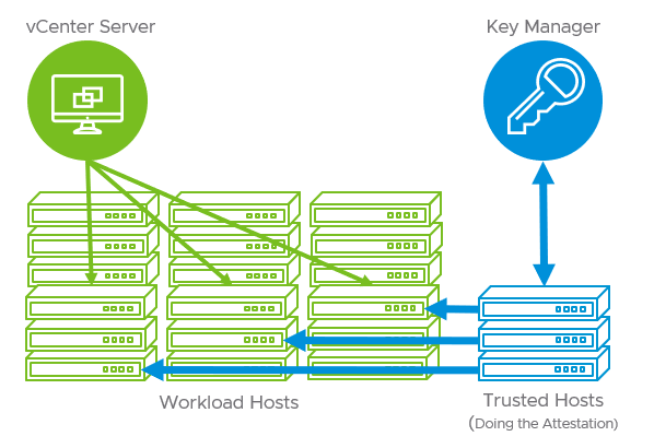

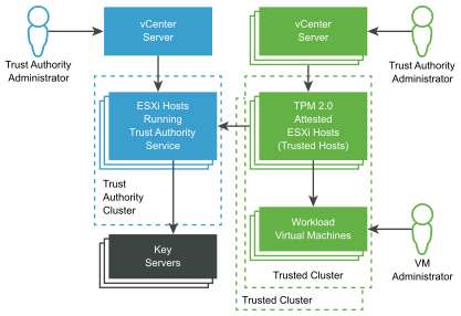
At VMware we talk a lot about intrinsic security, which is the idea that security in a vSphere environment is baked in to the product at a deep level, not sprinkled on as an afterthought.
One of the ways you see vSphere 7 improving intrinsic security is by allowing vSphere Admins to manage deeper into the infrastructure itself. You see Lifecycle Manager now able to work together with tools like Dell EMC OpenManage Integration for VMware vCenter and HPE iLO Amplifier to manage server firmware as part of the remediation cycles.
vSphere Trust Authority (vTA) is a tool to help ensure that our infrastructure is safe & secure.
Trusted Platform Module (TPM) 2.0 and the host attestation process.
TPMs do three things:
- The TPM serves as a cryptographic processor, and can generate cryptographic keys as well as random numbers.
- A TPM can store cryptographic materials, like keys, certificates, and signatures. It has techniques called “binding” and “sealing” that help control how the secrets it stores can be retrieved. Furthermore, to prevent people from physically stealing a TPM and accessing the secrets, TPMs are cryptographically bound to the server you first enable them on.
- A TPM can help us determine if a system’s integrity is intact by doing something called “attestation.” The TPM can measure and store security information, and then summarize it in a way that is very cryptographically strong. If a server has UEFI Secure Boot and its TPM enabled, vCenter Server can collect these security measurements and determine if the system booted with authentic software, and in a configuration we trust.
Software Guard Extensions
https://4sysops.com/archives/how-to-secure-data-with-vmware-virtual-software-guard-extensions-vsgx/
vSphere enables you to configure Virtual Intel Software Guard Extensions (vSGX) for virtual machines. Using vSGX enables you to provide additional security to your workloads.
How to enable and usge Software Guard Extensions (SGX)
vSGX enables virtual machines to use Intel SGX technology if available on the hardware.
To use vSGX
- the ESXi host must be installed on an SGX-capable CPU
- SGX must be enabled in the BIOS of the ESXi host
- You can use the vSphere Client to enable SGX for a virtual machine
Limitations of Virtual Software Guard Extensions (SGX) in vSphere (71367) https://kb.vmware.com/s/article/71367
Virtual Standard Switch (VSS) advanced virtual networking options
While vSphere 7 does not offer any significant changes or new networking capabilities, it does offer the ability to run vSphere with Kubernetes, which previously involved NSX-T installation.
vSphere 7, or rather vCenter Server 7, offers a new capability called Multi-homed NICs, which allow having multiple management interfaces for vCenter and fulfilling different network configuration and segmentation needs.
Configure load balancing on VSS (virtual standard switch)
Remember, those are per-vSwitch settings, so if you have three hosts in the cluster, you must replicate those settings manually across all your hosts. Hence, the advantage of distributed vSwitch.
- Route based on originating virtual port
- Route based on source MAC hash
- Route based on IP hash
- Use Explicit Failover Order
vSphere 7 – Identity Federation
https://blogs.vmware.com/vsphere/2020/03/vsphere-7-identity-federation.html
vSphere 7 has Identity Federation. Identity Federation allows us to attach vCenter Server to enterprise identity providers like Active Directory Federation Services (ADFS). This means that vCenter Server participates in the same centralized corporate processes, such as onboarding and termination. It also means that users can use the same methods to log into vCenter Server as they do their desktops and the cloud. This includes MFA & 2FA solutions as well.

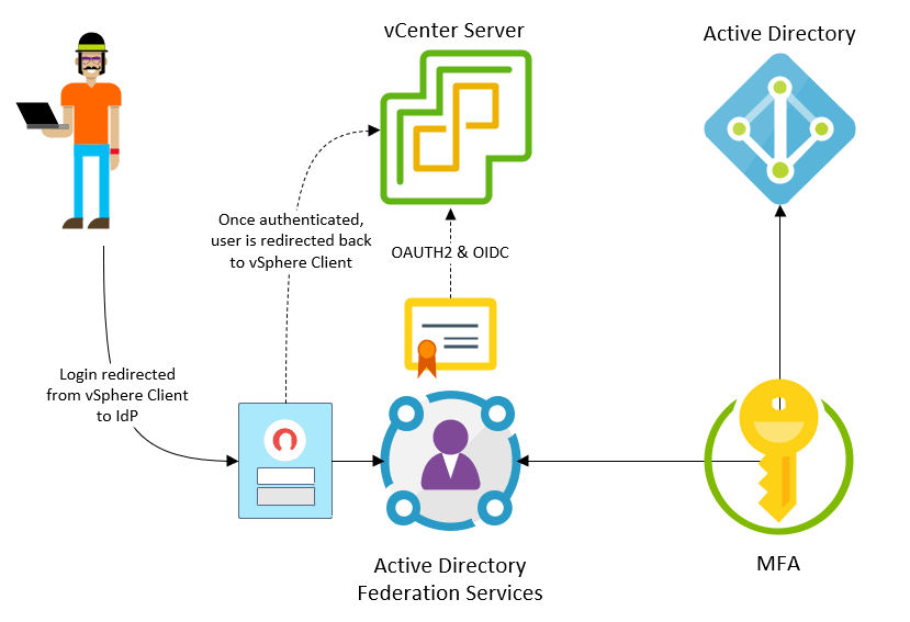
Datastore Cluster Design and Options
https://4sysops.com/archives/vsphere-7-and-the-configuration-of-storage-cluster-options/
A datastore cluster is a collection of datastores with shared resources and a shared management interface. Datastore clusters are to datastores what clusters are to ESXi hosts. After you create a datastore cluster, you can use vSphere Storage DRS to manage storage resources.
The following resource management capabilities are also available for each datastore cluster.
Capability                          Description
Space utilization load balancing    You can set a threshold for space use. When space use on a datastore exceeds the threshold,
                                    vSphere Storage DRS generates recommendations or performs migrations with vSphere Storage vMotion
                                    to balance space use across the datastore cluster.
I/O latency load balancing          You can configure the I/O latency threshold to avoid bottlenecks.
                                    When I/O latency on a datastore exceeds the threshold, vSphere Storage DRS generates recommendations
                                    or performs vSphere Storage vMotion migrations to help alleviate high I/O load.
Anti-affinity rules                 You can configure anti-affinity rules for virtual machine disks to ensure that
                                    the virtual disks of a virtual machine are kept on different datastores.
                                    By default, all virtual disks for a virtual machine are placed on the same datastore.
As a good practice, the datastore cluster should remain homogeneous, it means that all datastores are the same type, such as VMFS, or NFS, but not mix together.
# Storage cluster options
1. In vSphere client, select the relevant datacenter inventory.
2. Right-click and select Datacenter > Storage > New Datastore Cluster
3. On the New Datastoer Cluster configuration page, select "Turn ON storage DRS", click Next
4. On the next page, select between Fully Automated or No Automation (Manual mode)
    Select options:
    a. Space balance automation level
    b. I/O balance automation level
    c. Rule enforcement automation level
        Specifies SDRS behavior when it generates recommendations for correcting affinity rule violations in a datastore cluster.
    d. Policy enforcement automation level
    e. VM evacuation automation level
5. Storage DRS Runtime Settings
    a. I/O Metric Inclusion
    b. I/O latency threshold
    c. Space threshold
6. Select Clusters and Hosts
    Select the cluster and hosts that will be part of the cluster
7. Select Datastores
    Shows which datastores can be used
ESXi host time synchronization
If you see the exchange between your esxi host and external ntp server over tcpdump-uw, then the problem is not in your firewall
# You can check state ntpd service by command
    /etc/init.d/ntpd status

# VIClient
    Host - Configuration - Time Configuration

# Also you can use ntpq - standard NTP query program, usually useful output command
    ntpq -pn
        It will show the following information
        remote          refid       st  t   when    poll    reach   delay   offset  jitter
        ------------------------------------------------------------------------------------
        *<NTP-server>   <NTP-ip>    2   u    41     64      377     1.242   4.143   0.459

        Where
            remote      It is the ntp server that is used
            refid       The actual NTP server, the next hop from remote
            st          server's stratum
            t           type - unicast, broadcast, multicast, or manycast
            poll        How often the server will be polled, 64 seconds is normally used
            reach       The number is in octal, so eigth success in octal will be represented by 377
            offset      Difference between the local clock and the server's clock, in milliseconds
            jitter      Refers to the network latency between the server and ntp server

    watch "ntpq -p <esxi_ip_address>"

# Check the contents of the file
    /etc/ntpd.conf & /etc/ntpd.drift

# Watch the updated message when restart ntpd
    tail -fq /var/log/messages
    /etc/init.d/ntpd restart

# check hwclock
Networking commands for ESXi host - ssh
https://www.tunnelsup.com/networking-commands-for-the-vmware-esxi-host-command-line/
If you have ssh access to a VMWare ESXi server these commands can help you navigate the different networking settings on the server.
# list available network ip options
esxcli network ip
    dns
    interface
    ipsec
    route
    connection
    neighbor

esxcli network ip interface list    # show interface details
esxcli network ip interface ipv4 get    show ip address of each interface and subnet mask
esxcfg-nics -l      # show the physical status of the interface,
                        including if the link is up, MAC and speed of the interface
network ip route ipv4 list      # show the routing details
esxcfg-route        # just show the default gateway
Reboot and shut down ESXi host with esxcli
https://kb.vmware.com/s/article/1013193
You can shut down or reboot an ESXi host by using the vSphere Web Client or vCLI commands, such as ESXCLI or vicfg-hostops
# Prerequisite
1. Enter the ESXi host in maintence mode    # This is important
2. SSH to ESXi host

# To reboot or shut down the host using the vSphere Web Client:
1. From the vSphere Web client, navigate to the host you want to shut down.
2. Right-click the host and click Reboot or Shutdown.

# To reboot or shut down the host using esxcli
esxcli system shutdown poweroff --reason <Enter Reason>     # Shutdown now
esxcli system shutdown poweroff --reason <Enter Reason> --delay <seconds>

esxcli system shutdown reboot --reason <Enter reason>   # reboot
esxcli system shutdown reboot --reason <Enter reason> --delay <seconds>
How to identify unassiciated vSAN objects
There are many instances of what gets classed as an Unassociated object, the below are typical examples and not an exhaustive list:
- Any VM data objects (e.g. namespace, vmdk, snapshot, vswap, vmem) of a VM that is not currently registered in vSphere inventory.
- vSAN iSCSI target vmdk and namespace objects.
- Content Library namespace objects.
- vSAN stats objects used for storing vSAN Performance data.
- vswp objects belonging to some appliance e.g. NSX controllers, vRLI appliances and vROPS appliances.
#Run RVC command
    vsan.obj_status_report -t <pathToCluster>

Identification can also be done via PowerCLI.

Note:
1. Unassociated does not necessarily mean unused/unneeded.
2. Prior to performing any actions that could potentially cause loss of data such as deleting vSAN objects,
    care should always be taken to positively identify the Object(s) and confirm that they are not needed and are safe to delete.
VM snapshot
# Verify VM snapshots
1. ssh to ESXi host
2. cd /vmfs/volumes/<vsanDatastore>/<VM-name>
3. ls -l    # This will show all the files that make up the VM
vmkfstools is one of the ESXi Shell commands for managing VMFS volumes, storage devices, and virtual disks. You can perform many storage operations using the vmkfstools command. For example, you can create and manage VMFS datastores on a physical partition, or manipulate virtual disk files, stored on VMFS or NFS datastores.
# vmfstool command
vmfstools -qv10 <vm.vmdk>

# Verify vmx file
cp <vm.vmx>  <vm..vmx.bak>    # Make a copy of the vmx file before making any changes
vi <vm.vmx>     # Update the vmx file if required

Note:
After you make a change using the vmkfstools, the vSphere Client might not be updated immediately.
Use a refresh or rescan operation from the client
Best practices for using VMware snapshots in the vSphere environment (1025279)
https://kb.vmware.com/s/article/1025279
Troubleshooting issues resulting from locked virtual disks (2107795)
https://kb.vmware.com/s/article/2107795
vSphere ESXi VIB Upgrade
https://kb.vmware.com/s/article/2008939
# Verify storage and network adapter list
esxcli storage core adapter list    # Verify storage core adapters
esxcli network nic list     # verify network adapter list

# Upload the VIB (zip file) to datastore folder
Upload from vSphere client

# Verify VIB files in datastore
ssh to ESXi host
cd /vmfs/volumes/<datastore>/<folder>
ls -l   # verify the VIB zip files

# Monitor ESXi update process for any error or issue
tail -f /var/log/esxupdate.log

# Remove the VIB and then install new VIB
esxcli software vib list | grep "<Required-VIB>"
    esxcli software vib list | grep "nhpsa"
esxcli software vib remove -name "<vib-name>
    esxcli software vib remove -name "nhpsa"    # example

# Install the update VIB
esxcli software vib install -d /tmp/<vib-file.zip>
    esxcli software vib install -d /vmfs/volumes/<LUN>/<folder>/<vib-file.zip>
esxcli software list list --rebooting-image     # verify the new VIB in the rebooting image

# Reboot ESXi host
reboot      # Alternative   esxcli system shutdown reboot --reason "Reaason"

# Take system off maintenance mode, after reboot
vim-cmd hostsvc/maintenance_mode_exit
How to create NFS datastore for cluster
# Pre-requisite
1. Setup the NFS share folder in NFS server

# Process
1. In vSphere client, select the cluster
2. On right pane, click Action -> Storage -> New Datastore
3. Select datastore type
    a. VMFS
    b. NFS  <--- Select NFS
    c. Vvol
4. NFS version
    a. NFS 3
    b. NFS 4
5. Name and Configuration
    a. Name     # datastore name, such as ds-nfs-cluster-name
    b. Folder   # NFS share folder name
    c. Server   # NFS server FQDN or IP
6. Host Accessibility
    Select all ESXi hosts   # Ensure all ESXi host have access to the new datastore
How to change ESXi host ScratchConfig location
1. In vSphere client, select the required ESXi host
2. On right pane, select Config -> System -> Advanced System Settings
3. Search and locate ScratchConfig.ConfiguredScratchLocation
4. Update value
    /vmfs/volumes/<datastore-uid|NFS-datastore-uid>/.locker_hostname
        # Hostname need to be short name or netbios name, it can't contain "." in the name
5. Reboot ESXi host to take effect
How to un-register and re-register VM
https://kb.vmware.com/s/article/1005051
# SSH to ESXi host
1. SSH to the ESXi host where the VM locates
2. run vim-cmd command    # CLI command
    vim-cmd vmsvc/getallvms     # note down vmid of the required VM
        Note: run  esxtop   and then press  shift + v  keys to show virtual machines and running ID on the ESXi host

Note
    To unregister the VM from the ESXi hosts on which it is registered but not running
        vim-cmd  vmsc/ungister  <vmid>

    If the VM has a process (PID) associated with it, ESXi host may not allow you to unregister and command fails
        Ensure the VM is fully powered OFF, then
            vim-cmd  vmsc/unregister <vmid>     # try to unregister it again

# From vCenter / vSphere Client
1. Note down the VMware path / location of vmx file
1. Locate the required VM from vCenter
2. Ensure the VM is powered off
3. Right click the required VM, and select Remove from Inventory

#*** Process a single VM ****
# PowerCLI  - This is useful when working with vSAN
$RequiredVM = Get-VM -Name "VM-Name"

$Name = $RequiredVM.Name
$ResourcePool = $RequiredVM | Get-ResourcePool
$Folder = $RequiredVM.Folder
$VMSFile = $RequiredVM.ExtensionData.config.Files.vmpathname

# Stop the VM before un-register the VM
Stop-VM $RequiredVM -Kill -Verbose -Confirm:$false      # Remove -kill  parameter if VM is healthy
$RequiredVM | Remove-VM -Confirm:$false -Verbose        # un-register VM

# Re-register the VM
New-VM -VMFilePath $VMSFile -ResourcePool $ResourcePool -Location $Folder -Verbose
Get-VM -Name $Name | Start-VM -RunAsync -Verbose

#**** Process multiple VMs ****
$VMList = 'Server1','Server2'

Get-VM -Name $VMList | ForEach-Object -Process {
    $Name = $PSItem.Name
    $ResourcePool = $PSItem | Get-ResourcePool
    $Folder = $PSItem.Folder
    $VMSFile = $PSItem.ExtensionData.config.Files.vmpathname

    # Stop the VM before un-register the VM
    Stop-VM $PSItem -Kill -Verbose -Confirm:$false      # Remove -kill  parameter if VM is healthy
    $PSItem | Remove-VM -Confirm:$false -Verbose        # un-register VM

    # Re-register the VM
    New-VM -VMFilePath $VMSFile -ResourcePool $ResourcePool -Location $Folder -Verbose
    Get-VM -Name $Name | Start-VM -RunAsync -Verbose
}
How to remove orphaned VM from vCenter
# PowerCLI
Remove-VM vm_name -deletepermanently

# CLI
vim-cmd vmsc/destroy  <vmid>     # vmid of the required orphaned VM
Cross vCenter vMotion
If you remember a very popular VMware fling called Cross vCenter server vMotion, you should know, that its functionality now has been completely integrated into vSphere web client. What previously had to be done via this external Fling software, now, starting with vSphere 7 U1c you can use simply your vSphere web client.
Quote from VMware Flings site:
This Fling has been productized and is now part of the vSphere 7.0 Update 1c release. For vSphere 6.x-to-6.x Migration, this Fling can still be used but for newer migrations, it is recommended that you use the official Advanced Cross vCenter vMotion feature included in vSphere 7.0 Update 1c.
Additionally, vSphere 7.0 U3c has added another improvement where you can now execute a clone bulk operation between vCenter servers residing in different SSO domains. And this isn’t well known widely so that’s why this post is nicely reminder.
The goal of the enhancements brought by VMware is simple. To give you a smooth possibility of migrating workloads between different sites with different SSO domains in case you acquiring another branch, another company or migrating to/from cloud environments.
You can do workload migrations from an on-prem vSphere infrastructure to VMware Cloud on AWS, or when migrating from VMware Cloud Foundation (VCF) 3 to VCF 4.
What’s important is the fact that advanced Cross vCenter vMotion (XVM) does not depends on vCenter Enhanced Linked Mode or Hybrid Linked Mode.
Advanced vCenter vMotion works for both on-premise and cloud environments.
Starting vCenter Server 7.0 Update 1c, when you use your vSphere Web Client, you can use the Advanced Cross vCenter vMotion do a different task.
With latest vSphere 7.0 Update 3 you can also do vMotion/clone operations between two different SSO domains.
Cross vCenter Migration and Clone requirements
vSphere 6.x and higher – The Advanced Cross vCenter vMotion (XVM) feature in vSphere 7.0 U1c is only supported between vSphere (vCenter and ESXi) instances 6.5 or greater. (vSphere 6.0 builds are not supported).
Ent Plus Licensing – The cross vCenter Server and long distance vMotion features require an Enterprise Plus license.
Time In Sync – Both vCenter Server instances must be time-synchronized with each other for correct vCenter Single Sign-On token verification.
# Network ports requirements
8000 and 902 for vMotion and NFC between ESXi.
443 between both vCenter Servers.
443 between vCenter Server and the ESXi server (this is a requirement to have the ESXi host added to vCenter Servers).
https://www.altaro.com/vmware/cross-vcenter-vmotion/
Considerations and prerequisites If you are having trouble getting Cross-vCenter vMotion to work, review the following prerequisites to ensure your environment supports it. And because there is no point in re-writing everything here, refer to the documentation for an exhaustive list of the various caveats. Below are the main ones.
vSphere License An Enterprise Plus license is required to use Cross-vCenter vMotion.
Versions Note that the type of migration you can do (clone, cold or live) will depend on the versions you run. More information in the documentation.
Enhanced Linked Mode: vSphere version 6.0 or later. Different SSO domains: Advanced Cross vCenter vMotion, introduced in vSphere 7.0 U1c, is only supported between vSphere (vCenter and ESXi) versions 6.5 or greater. The source vCenter must run vCenter 7.0 U1c or later.
PowerCLI (vSphere 6.0 and above)
If you haven’t upgraded to, at least, vCenter 7U1c, you can still migrate VMs to a vCenter in a different SSO domain using the methods mentioned earlier. You can either use the community fling or PowerCLI. We will demonstrate the latter in this section.
You will find examples in the help section of the Move-VM cmdlet in PowerCLI.
We are demonstrating here a basic migration with the minimum requirements. You can always tune it if you use storage policies, distributed switches and so on.

1. First, you need to ensure you can be connected to multiple vCenter servers.
Set-PowerCLIConfiguration -DefaultVIServerMode Multiple -Confirm:$False

2. Connect to both vCenter servers in your PowerCLI session.
$SourceVC = Connect-VIServer ‘core-vc.lab.priv’ -Credential (Get-Credential -Message “Source vcenter creds”)
$DestVC = Connect-VIServer ‘site-b-vcenter.lab.priv’ -Credential (Get-Credential -Message “Destination vcenter creds”)

3. Select the virtual machine and its virtual NIC. You can use the -Server parameter to ensure the VM is on the source vCenter.

If the VM has multiple vNICs, make sure you know the order as the destination portgroups will need to be in the same order (vNIC[0] goes to PG[0], vNIC[1] goes to PG[1] and so on).

$vm = Get-VM -Server $SourceVC -name ‘Ubuntu21’
$vNIC1 = Get-NetworkAdapter -VM $vm

4. Select the host on the destination vCenter server along with the portgroup(s) and the datastore. Your mileage will vary here if you use distributed switches.
$DestVMHost = Get-VMHost -Server $DestVC -name “site-b-esx.lab.priv”
$DestPG1 = $DestVMHost | Get-VirtualPortgroup ‘VM Network’

$DestDS = $DestVMHost | Get-Datastore ‘Datastore1’

5. You can then execute the migration with Move-VM.
Move-VM -VM $VM -Destination $DestVMHost -NetworkAdapter $vNIC1 -PortGroup $DestPG1 -Datastore $DestDS